13
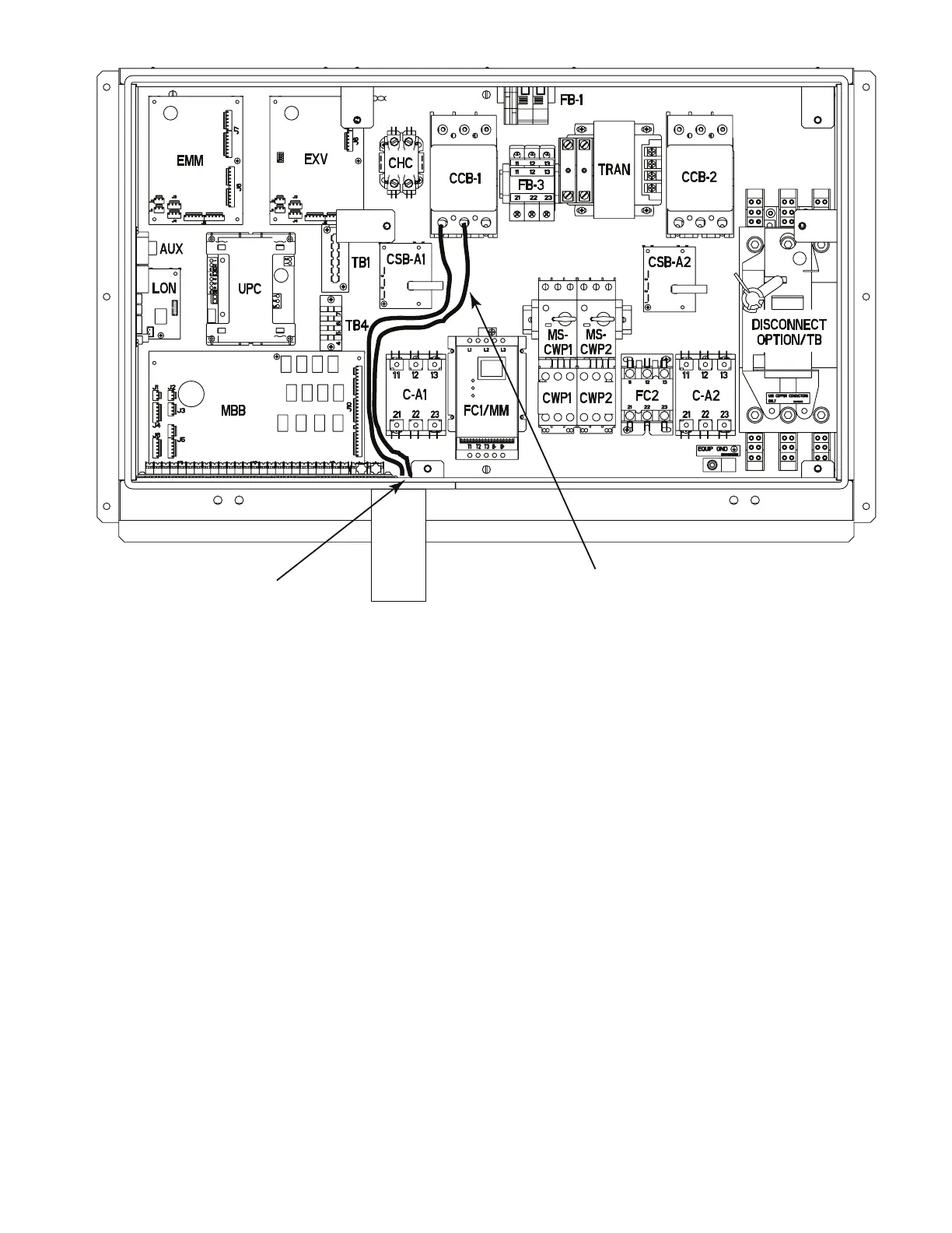
Fig. 17 — Tank Power Connections
OPERATION
A thermostat is mounted within the tank heater control box to reg-
ulate the water temperature. The thermostat is set to 55°F with a
deadband of 5°F. When a call for the heating is made, the heater
will turn on at 50°F and off at 55°F.
Restore power to the main unit and check heaters for proper oper-
ation. The tank heaters are in an operative state when the Emer-
gency On-Off switch on the chiller is in the OFF position, and the
thermostat is in closed position.
The tank heaters are wired in the control circuit so that they are op-
erable as long as the main power to the chiller is ON. A factory-in-
stalled and set overload device protects them.
NOTE: The field-supplied disconnect should never be off except
when the tank accessory and/or chiller are being serviced or are to
be down for a prolonged period, in which case the accessory tank
and chiller should be drained.
Storage tank pressure drop pressure drop curves are shown in
Appendix A.
EMM
EXV
CCB-1
TB1
TB4
CHC
AUX
LON
UPC
FC1/MM
CSB-A1
MBB
C-A1
FB-3
TRAN
CCB-2
CSB-A2
DISCONNECT
OPTION/TB
FC2 C-A2
FB-1
CWP1CWP2
MS-
CWP1
MS-
CWP2
Conduit
Typical Power
Wiring Path
BLK and YEL
Power Wires
 Loading...