7
Step 2 — Connect Cooler Fluid and Drain Piping
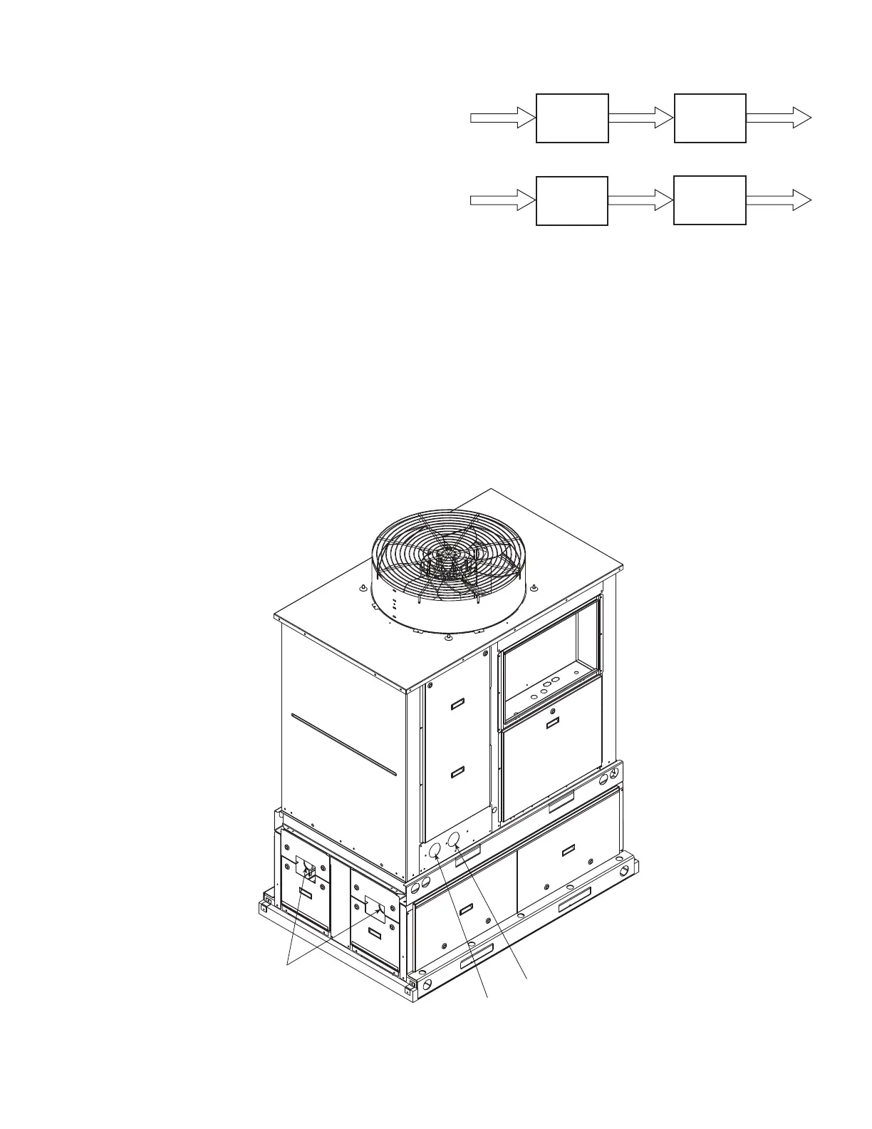
The piping between the chiller and the accessory tank can be done
to allow the tank to be on the return side of the chiller (tank piped
to chiller inlet) or the supply side of the chiller (tank piped to the
chiller outlet). See Fig.
6. However, it is recommended that the
tank be piped to the return side of the chiller to buffer any changes
in load to allow more stable chiller operation. For digital compres
-
sor applications, it is recommended that the tank be piped to the
supply side of the chiller to provide a more stable supply tempera
-
ture. See Fig. 7 and 8 for an examples of piping layouts.
All sizes have 2-1/2 in. Victaulic connections. Provide a means of
venting air from the high point of the field-installed piping as re
-
quired. All sizes also have 2 in. drains at the bottom of each end of
the storage tanks. This size has been provided to allow cleaning of
foreign material that may collect at the bottom of the tanks.
After field piping is complete, freeze protection is recommended
using inhibited ethylene glycol or other suitable inhibited anti-
freeze solution and electric heat tapes in area where piping is ex-
posed to low ambient temperatures (34°F [1°C] or below). Heat
tapes should be rated for area ambient temperatures and be cov-
ered with a suitable thickness of closed-cell insulation. Route
power for heating tapes from a separately fused disconnect. Identi
-
fy disconnect as heat tape power source with a warning that power
must not be turned off except when unit is being serviced.
PREPARATION FOR YEAR-ROUND OPERATION
If unit is in operation year-round, add sufficient inhibited ethylene
glycol or other suitable inhibited antifreeze solution to chilled wa
-
ter to prevent freezing under low-ambient operating conditions.
Consult local water treatment specialist on characteristics of water
and recommended inhibitor.
Fig. 6 — Typical Chiller/Tank Setup
PREPARATION FOR WINTER SHUTDOWN
Do not shut off electrical disconnect during off-season shutdown.
At end of cooling season:
1. Make sure LOCAL/OFF/REMOTE switch is in the OFF
position on the chiller.
2. Drain water from the accessory tank system.
3. Replace drain plugs and fill tanks with a rust inhibiting anti-
freeze solution to prevent freezing of residual water and rust
build-up.
4. At beginning of the each cooling season, refill cooler and add
recommended inhibitor.
Fig. 7 — Typical Piping Layout — 30RA-900---050,051
Accessory
Tank
Recommended Piping Scheme
Alternate Piping Scheme
30RAP
Chiller
Accessory
Tank
30RAP
Chiller
Water
Inlet
Tank
Inlet/Outlet
Water
Outlet
 Loading...