8
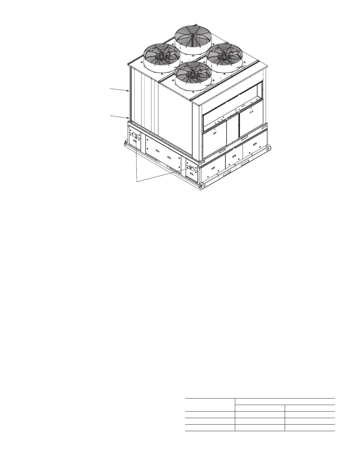
Fig. 8 — Typical Piping Layout — 30RA-900---052
Step 3 — Make Electrical Connections
POWER SUPPLY
The storage tank does not require a power connection to the tank
heater if the chilled fluid has been properly treated with a suitable
anti-freeze solution or the chilled fluid is drained during the winter
season. If this is the case, installation is complete and the tank
electric heater is not used.
ELECTRIC HEAT
The water storage tanks are provided with electric heaters to pre-
vent freeze-up during low ambient temperature conditions. The
heaters will provide freeze protection to –20°F (–28.9°C). Care
must be taken to prevent freeze-up in the event of a power loss.
CONDUIT CONNECTION
The tank power is provided from the main unit control box. Con-
duit is supplied in the accessory kit which needs to be installed be-
tween the main control box and the tank heater control box. Per-
form the following steps to install the conduit:
1. Make a 0.75 in. (19 mm) diameter hole using a drill or punch
per Fig. 9-11.
2. Knock out the conduit entry hole in the tank control box. See
Fig. 12.
3. Remove the conduit connector from the end of the conduit
opposite the end with ring terminals.
4. From inside the compressor section of the unit, feed the con-
duit through 0.75 in. (19 mm) hole made in Step 1.
5. Route the conduit between storage tanks to the storage con-
trol box and install connector removed in Step 3.
6. Make conduit connection to power entry hole in tank control
box shown in Fig. 12.
7. Make power connections in tank control box to TB1A. Con-
nect black wire to terminal 11. Connect yellow wire to termi-
nal 12. Connect green wire to ground connection.
8. Connect red and brown control wires from conduit to red and
brown wires in tank control box using wire nuts supplied in
hardware kit.
9. Check tank heater wiring for proper termination. See Fig. 13.
Accessories are shipped from the factory for high voltage
wiring and if applied at 208/230 volts, will not have freeze
protection down to –20°F (–28.9°C). A warning label is
affixed to the tank to alert installers if the power supply is
208/230 volts. See Fig. 14. For 208/230 v units, the heater
elements must be wired in parallel instead of series. Recon-
nect the black, red, and white wires in the tank heater wiring.
See Fig. 13.
NOTE: Tank heater wiring in both control boxes (control box
1 and 2) must be changed for the 30RA-900---052 accessory.
10. Relocate HPS and EXV wires for sizes 015-030 and HPS-B
wires for sizes 035-060 to compressor wire entry. See Fig. 15
and 16.
11. Route the end of the conduit assembly through the hole used
for the HPS entry into the control box. Use the adapter
washer provided with the hardware kit.
12. Make power connections to appropriate compressor circuit
breaker as required. See Table 3 and Fig. 17.
13. Make control wire connection with RED and BROWN wires
from conduit to wires labeled TNKR-HTR (RED) and
TNKR-COM (BRN) located next to the low voltage terminal
strip in main control box.
Table 3 — Compressor Circuit Breakers
Tank
Inlet/outlet
Water
Inlet
(Hidden)
Water
Outlet
(Hidden)
30RAP
UNIT SIZE
CONNECTION
BLK WIRE YEL WIRE
010,015 CCB-1-21 CCB-1-22
018-030 CCB-1-21 CCB-1-22
035-060 CCB-3-21 CCB-3-22
 Loading...