EasyManua.ls Logo

Carrier 38MARBQ12AA3 User Manual

Carrier 38MARBQ12AA3
116 pages
To Next Page IconTo Next Page
To Previous Page IconTo Previous Page
Page #4 background imageLoading...
Page #4 background image
4 Specifications subject to change without notice. SG-38MARB-01
DIMENSIONS AND WEIGHTS
Table 3 — Dimensions and Weights
Fig. 1 — Size 12K (115V)
SYSTEM SIZE
12K 9K 12K 18K 24K 30K 36K
(115 V) (208/230 V) (208/230 V) (208/230 V) (208/230 V) (208/230 V) (208/230 V)
OUTDOOR UNIT
Unit
Height (H) in (mm) 21.85 (555) 21.81 (554) 21.81 (554) 26.50 (673) 31.89 (810) 31.89 (810) 31.89 (810)
Width (W) in (mm) 30.12 (765) 31.69 (805) 31.69 (805) 35.04 (890) 37.24 (946) 37.24 (946) 37.24 (946)
Depth (D) in (mm) 11.93 (303) 12.99 (330) 12.99 (330) 13.46 (342) 16.14 (410) 16.14 (410) 16.14 (410)
Weight -
Net
lbs. (kg) 66.80 (30.3) 74.07 (33.6) 73.63 (33.4) 100.97 (45.8) 134.48 (61) 141.76 (64.3) 150.13 (68.1)
PACKAGING
Height in (mm) 24.02 (610) 24.21(615) 24.21 (615) 29.13 (740) 34.84 (885) 34.84 (885) 34.84 (885)
Width in (mm) 34.92 (887) 36.02 (915) 36.02 (915) 39.17 (995) 42.91 (1090) 42.91 (1090) 42.91 (1090)
Depth in (mm) 13.27 (337) 14.57 (370) 14.57 (370) 15.67 (398) 19.69 (500) 19.69 (500) 19.69 (500)
Weight -
Gross
lbs. (kg) 72.31 (32.8) 80.25 (36.4) 79.37 (36) 108.03 (49) 144.40 (65.5) 151.90 (68.9) 158.95 (72.1)
Carton
Drawing
No.
-- 877*327*590 905*360*590 905*360*590 985*388*720 1075*485*86 1075*485*86 1075*485*86
CARTON MATERIAL
Material
Thickness
in (mm) 0.197 (5) 0.197 (5) 0.197 (5) 0.197 (5) 0.295 (7.5) 0.295 (7.5) 0.295 (7.5)

Table of Contents

Question and Answer IconNeed help?

Do you have a question about the Carrier 38MARBQ12AA3 and is the answer not in the manual?

Carrier 38MARBQ12AA3 Specifications

General IconGeneral
BrandCarrier
Model38MARBQ12AA3
CategoryHeat Pump
LanguageEnglish

Summary

INTRODUCTION

MODEL / SERIAL NUMBER NOMENCLATURES

SPECIFICATIONS - HEAT PUMP

DIMENSIONS AND WEIGHTS

CLEARANCES

ELECTRICAL DATA

WIRING

Provides guidelines for power and communication wiring connections.

CONNECTION DIAGRAMS

WIRING DIAGRAMS

FAN AND MOTOR SPECIFICATIONS

REFRIGERATION CYCLE DIAGRAMS

REFRIGERANT LINES

SYSTEM EVACUATION AND CHARGING

Deep Vacuum Method

Explains the deep vacuum method for system evacuation using a vacuum pump.

Triple Evacuation Method

Outlines the triple evacuation method for system evacuation.

Final Tubing Check

Instructions for checking tubing integrity before final assembly.

ELECTRONIC FUNCTIONS

Main Protection

Details main protection functions like compressor restart delay and high temp cutout.

Operation Modes and Functions

Explains operation modes (FAN, COOLING) and compressor/fan running rules.

FAN Mode

Describes the unit's operation in FAN mode.

COOLING Mode

Covers compressor and outdoor fan running rules in COOLING mode.

Indoor Fan Running Rules

Defines indoor fan operation rules for COOLING and HEATING modes.

Compressor Temperature Protection

Explains compressor temperature protection mechanisms.

Evaporator Temperature Protection

Describes evaporator temperature protection that stops the compressor.

HEATING Mode

Details compressor and outdoor fan running rules for HEATING mode.

Evaporator Coil Temperature Protection

Describes evaporator coil temperature protection that stops the compressor.

AUTO Mode

Explains AUTO mode selection and unit behavior.

DRYING mode

Details the DRYING mode operation and low room temperature protection.

FORCED OPERATION Function

How to enter and use forced operation modes (AUTO, COOLING).

Operation Rules

Explains operation rules for FORCED COOLING and FORCED AUTO modes.

AUTO-RESTART function

Describes the auto-restart function after a power failure.

Refrigerant Leakage Detection

Details refrigerant leakage detection and its display indication.

46°F (8°C) Heating

Describes fan and compressor operation during 46°F (8°C) heating.

DEFROST Mode

Forced DEFROSTING Mode

Describes how to enter and exit the forced DEFROSTING mode.

Defrost Exit Conditions

Lists conditions that will cancel the DEFROST mode and revert to HEATING.

POINT CHECK FUNCTION

TROUBLESHOOTING

Safety

Important safety notes regarding electrical discharge before troubleshooting.

INDOOR UNIT DIAGNOSTIC GUIDES

DIAGNOSIS AND SOLUTION

Outdoor Unit Error Display

Details outdoor unit error displays and their corresponding solutions.

Outdoor EEPROM Parameter Error or Compressor Driven Chip EEPROM Parameter Error (EC51)

Troubleshooting for EEPROM parameter or compressor driven chip errors.

Indoor and Outdoor Unit Communication Error (EL01)

Troubleshooting for indoor/outdoor unit communication errors (EL01).

Zero Crossing Detection Error Diagnosis and Solution (EH02)

Troubleshooting for zero crossing detection errors (EH02).

The indoor fan speed is operating outside of the normal range (EH03)

Troubleshooting for indoor fan speed operating outside normal range (EH03).

DC Fan Motor (Control chip is in the fan motor)

Checks for DC fan motor voltage input and output.

The Outdoor Fan Speed is Operating Outside of Normal Range (EC07)

Troubleshooting for outdoor fan speed operating outside normal range (EC07).

Outdoor DC Fan Motor (DC motor that controls the chip on the PCB)

Procedures for checking outdoor DC fan motor resistance and voltage.

Indoor Temperature Sensor Is an Open Circuit or a Short Circuit (T1, T2) (EH60)

Troubleshooting for indoor temperature sensor faults (EH60).

Refrigerant Leakage Detection (EL0C)

Troubleshooting for refrigerant leakage detection (EL0C).

Indoor PCB/Display Board Communication Error (EH06)

Troubleshooting for indoor PCB/display board communication errors (EH06).

Current Overload Protection (PC08)

Troubleshooting for current overload protection (PC08).

IPM Malfunction or IGBT over-strong current protection (PC00)

Troubleshooting for IPM malfunction or IGBT over-current protection (PC00).

IPM Continuity Check

Procedure for checking IPM continuity.

Compressor Check

Procedure for checking compressor resistance.

Over voltage or low voltage protection (PC01)

Troubleshooting for over/low voltage protection (PC01).

Top temperature protection for compressor or High temperature or High pressure protection of IPM module (PC02)

Troubleshooting for compressor temp/IPM temp/high pressure protection (PC02).

Inverter compressor Drive Error (PC04)

Troubleshooting for inverter compressor drive errors (PC04).

Low Pressure Protection (PC03)

Troubleshooting for low pressure protection (PC03).

Indoor Units Mode Conflict (match with multi outdoor unit)

Describes mode conflicts between indoor units in multi-unit systems.

Communication Error Between Outdoor Main Chip and Compressor Driven Chip (PC40)

Troubleshooting for communication errors between outdoor main chip and compressor chip (PC40).

Check Procedures

Temperature Sensor Check

Procedure for checking temperature sensors using a multimeter.

Compressor Check

Procedure for checking compressor resistance values.

IPM Continuity Check

Procedure for checking IPM continuity.

4 - Way Valve Check

Procedure for checking the 4-way valve voltage and resistance.

EXV Check

Procedure for checking the Electronic Expansion Valve (EXV) winding resistance.

Main Parts Check

Temperature sensor checking

Procedure for checking temperature sensors and their resistance values.

Pressure on Service Port

System Pressure

DISASSEMBLY INSTRUCTIONS

Outdoor Unit Sizes 9-12K (115V) Panel Plate

Disassembly instructions for the outdoor unit panel plate.

Outdoor Unit Sizes 24K (208-230V)

Disassembly instructions for the outdoor unit panel plate (24K, 208-230V).

ELECTRICAL PARTS

PCB Board 2

PCB Board 3

PCB Board 4

PCB Board 5

PCB Board 6

PCB Board 7

PCB Board 8

PCB Board 9

PCB Board 10

PCB Board 11

PCB Board 12

Fan Assembly

Fan Motor

Steps to remove the fan motor.
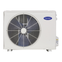
Sound Blanket

Four Way Valve (for heat pump models)

Compressor

SAFETY CAUTION

Appendix 1

Appendix 2

Appendix 3

Related product manuals