EasyManua.ls Logo

Carrier 38MARBQ30AA3 User Manual

Carrier 38MARBQ30AA3
116 pages
To Next Page IconTo Next Page
To Previous Page IconTo Previous Page
Page #10 background imageLoading...
Page #10 background image
10 Specifications subject to change without notice. SG-38MARB-01
WIRING DIAGRAMS
Fig. 10 — Wiring Diagram Size 12K (115V)
Table 6 — Wiring Diagram Size 12K (115V)
Table 7 — Wiring Diagram Size 12K (115V)
CN2/7/8 Input 230V AC
CN18 Output 0~12V DC
CN414 Output 0~310V AC
CN60 Output 230V AC
CN17 Output 0~5V DC
CN16 Output 230V AC
CN19 Output 230V AC
CN27/28/29 Output 0~310V AC
T3 Condenser Temperature Sensor
T4 Ambient Temperature Sensor
TP Discharge Temperature Sensor
NOTE
This symbol indicates that
the element is optional.
The actual shape shall prevail.

Table of Contents

Question and Answer IconNeed help?

Do you have a question about the Carrier 38MARBQ30AA3 and is the answer not in the manual?

Carrier 38MARBQ30AA3 Specifications

General IconGeneral
Model38MARBQ30AA3
TypeHeat Pump
Cooling Capacity (BTU/h)30000
Heating Capacity (BTU/h)30000
HSPF RatingUp to 9.5
Refrigerant TypeR-410A
Operating Voltage (VAC)208/230
Phase1

Summary

ELECTRICAL AND WIRING

Electrical Data

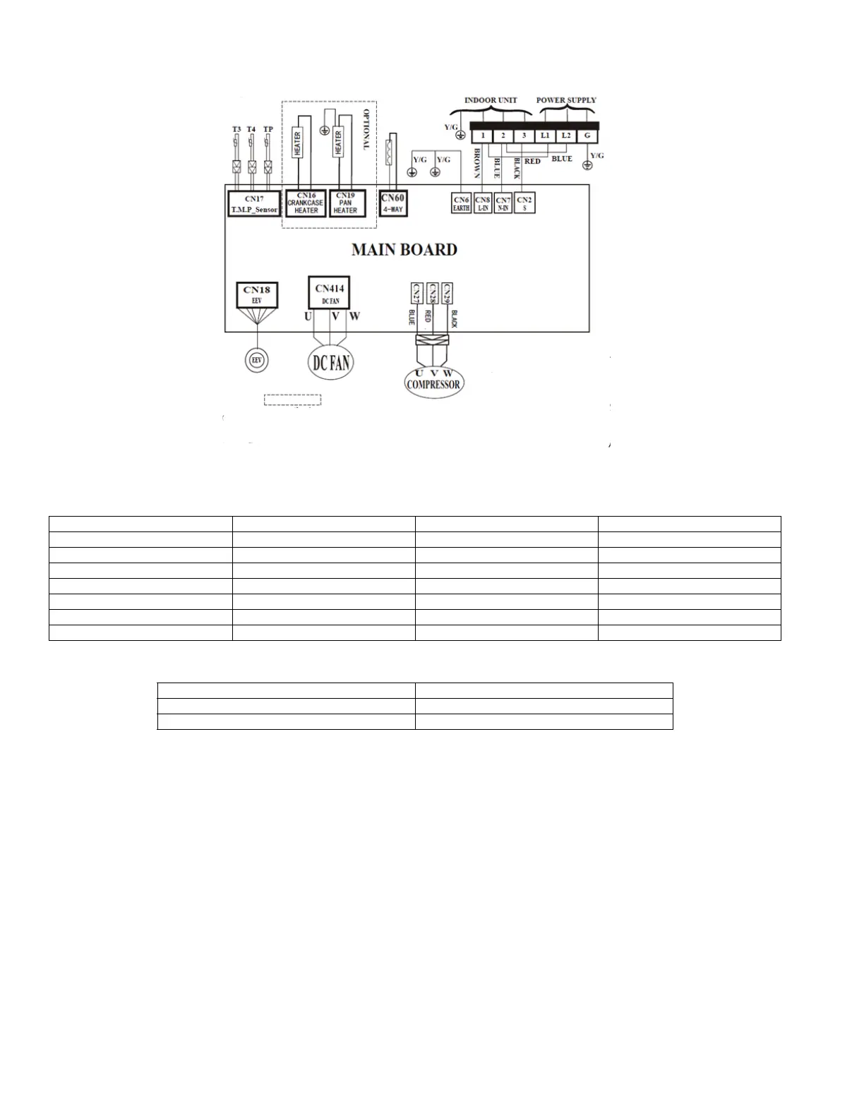
Key electrical data including voltage, current, and fuse ratings.

Wiring Diagrams and Connection Methods

Diagrams and recommended methods for unit wiring.

REFRIGERANT SYSTEM

Refrigeration Cycle Diagrams

Schematic diagrams illustrating the refrigerant cycle.

Refrigerant Lines and Charging

Guidelines for refrigerant line sizing, types, and charging.

DIAGNOSTICS AND TROUBLESHOOTING

Troubleshooting Safety and General Guides

Safety precautions and general troubleshooting advice.

SAFETY PRECAUTIONS

Related product manuals