11
INSTALLATION GUIDE
Up to five fan coil units can be connected to one outdoor unit.
Refer to the Product Data for approved combinations.
INSTALLATION TIPS
Ideal installation locations include:
Outdoor Unit
S A location which is convenient to installation and not exposed to
strong wind.
S A location which can bear the weight of the outdoor unit and
where the outdoor unit can be mounted in a level position.
S A location with appropriate clearances as outlined in Fig. 6.
S Do not install the indoor or outdoor units in a location with
special environmental conditions. For those applications, contact
your Ductless representative.
OUTDOOR UNIT INSTALLATION
1. Use a rigid base to support unit in a level position.
2. Locate outdoor unit and connect piping and wiring.
CAUTION
!
EQUIPMENT DAMAGE HAZARD
Failure to follow this caution may result in equipment
damage or improper operation.
Excessive torque can break flare nut depending on
installation conditions.
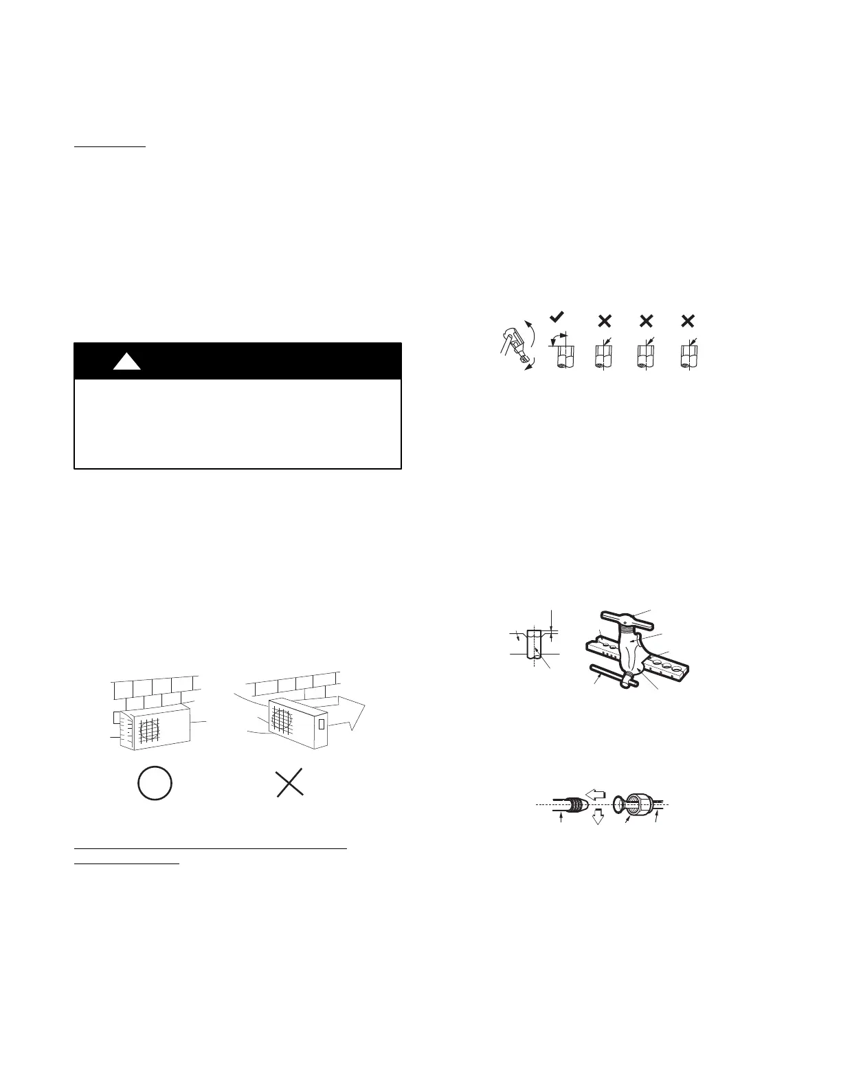
NOTE: Install the outdoor unit on a rigid base to reduce noise levels
and vibration. Determine the optimal air outlet direction to prevent
discharged air from being blocked. If the installation site is exposed to
strong winds such as a coastal areas, ensure the fan’s proper operation
by installing the unit lengthwise along the wall or use dust or shield
plates. If the unit needs to be suspended, the installation bracket should
comply with the suspension requirements in the installation bracket
diagram. The installation wall should be solid brick, concrete or the
same intensity construction, or take steps to reinforce and dampen the
support. The connection between the bracket and the wall as well as
the bracket and the air conditioner should be firm, stable and reliable.
Ensure there is no obstacle which may block the radiating air.
Strong
wind
A07350
Fig. 7 - High Wind Installation
MAKE REFRIGERANT PIPING CONNECTIONS
(OUTDOOR UNIT)
IMPORTANT: Use refrigeration grade tubing ONLY. No other
type of tubing may be used. Use of other types of tubing will void
the manufacturer’s warranty.
Piping Guide:
S Do not open service valves or remove protective caps from
tubing ends until all the connections are made.
S Bend tubing with bending tools to avoid kinks and flat spots.
S Keep the tubing free of dirt, sand, moisture, and other
contaminants
to avoid damaging the refrigerant system.
S Avoid sags in the suction line to prevent the formation of oil
traps.
Insulate each tube with minimum 3/8−in. (10 mm) wall thermal
pipe insulation.
Inserting the tubing into the insulation before
making
the connections saves time and improves installation quality.
1. The unit is equipped with multiple pairs of service valves.
Each pair is clearly marked (color and letter) to identify the
indoor unit circuits. In the outdoor unit wiring area, each
indoor unit interconnecting terminal block is marked (letter)
the same as the corresponding pair of service valves. The
indoor units must be piped and wired in matched sets (A to A;
B to B, etc.).
2. It is not required to use all of the available fan coil
connections if the application does not require them at the
current time. The system can be expanded at any time.
3. Conversion joints are supplied with the outdoor unit. They
are required for certain fan coil combinations. These joints
are to be connected to the outdoor unit as needed to match
the line set size.
4. Remove the service connection, if provided with the unit.
Oblique
DŽ
90
Roughness
Burr
A150767
Fig. 8 - Cut the Pipe
5. Remove all the burrs from the cut cross section of the pipe
avoiding any burrs inside the tubes.
6. Remove the flare nuts attached to the indoor and outdoor
units.
7. Install the correct size flare nut onto the tubing and make a
flare connection. Refer to Table 11 for the flare nut spaces.
Table 11—Flare Nut Spacing
OUTER DIAM. (mm)
A (mm)
Max. Min.
Ø1/4”(6.35) 0.05 (1.3) 0.03(0.7)
Ø3/8”(9.52) 0.06 (1.6) 0.04(1.0)
Ø1/2”(12.7) 0.07 (1.8) 0.04(1.0)
Ø5/8”(15.88) 0.09 (2.2) 0.08(2.0)
Bar
Copper pipe
Clamp handle
Red arrow mark
Cone
Yoke
Handle
Bar
"A"
A150768
Fig. 9 - Flare Nut Spacing
8. Apply a small amount of refrigerant oil to the flare
connection on the tubing.
9. Align center of the pipes and/or service valve.
Indoor unit tubing Flare nut Piping
A150769
Fig. 10 - Align Pipe Center
10. Connect both the liquid and gas piping to the indoor unit
11. Tighten the flare nut using a torque wrench as specified in
the Table 12.
12. Complete the installation.
Table 12—Tightening Torque
PIPE DIAMETER
INCH (mm)
TIGHTENING TORQUE
Ft-lb N-m
Ø1/4” (6.35) 10 to 13 13.6 to 17.6
Ø3/8” (9.52) 24 to 31 32.5 to 42.0
Ø1/2” (12.7) 37 to 46 50.1 to 62.3
Ø5/8” (15.88) 50 to 60 67.7 to 81.3
 Loading...