12
INSTALL ALL POWER AND INTERCONNECTING
WIRING TO OUTDOOR UNIT
1. Mount outdoor power disconnect.
2. Run power wiring from main box to disconnect per NEC
and local codes.
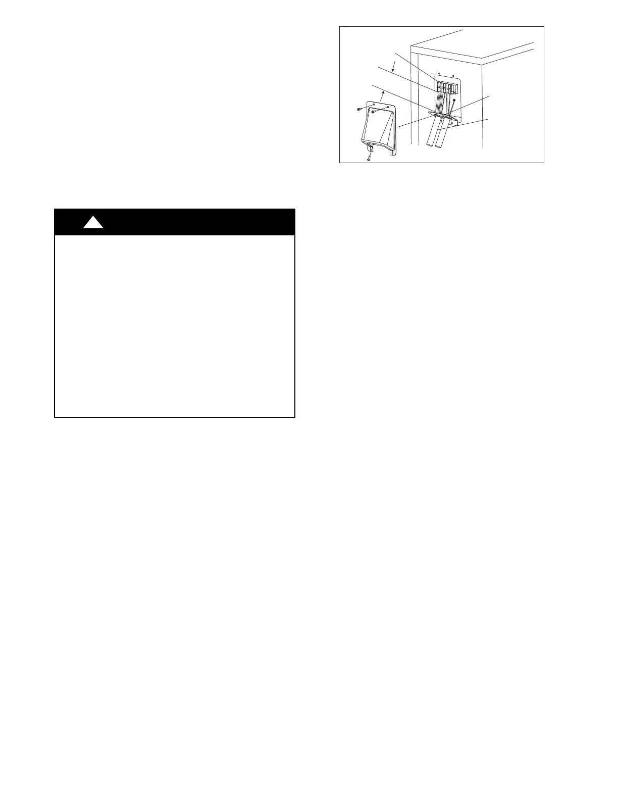
3. Remove field wiring cover (if available) from unit by
loosening screws.
4. Remove caps on conduit panel.
5. Connect the conduit to the conduit panel (see Fig. 11).
6. Properly connect both power supply and control lines to
terminal block per the connection diagram.
7. Ground unit in accordance with NEC and local electrical
codes.
8. Use lock nuts to secure conduit.
9. Reinstall field wiring cover.
CAUTION
!
EQUIPMENT DAMAGE HAZARD
Failure to follow this caution may result in equipment
damage or improper operation.
S Be sure to comply with local codes while running wire
from indoor unit to outdoor unit.
S Every wire must be connected firmly. Loose wiring may
cause terminal to overheat or result in unit malfunction. A
fire hazard may also exist. Therefore, be sure all wiring is
tightly connected.
S No wire should be allowed to touch refrigerant tubing,
compressor or any moving parts.
S Disconnecting means must be provided and shall be
located within sight and readily accessible from the air
conditioner.
S Connecting cable with conduit shall be routed through
hole in the conduit panel.
Over 1.57" (40mm)
Terminal Block
Conduit panel
Conduit
Outdoor unit
A07455
Fig. 11 - Field Wiring
ELECTRICAL DATA
Table 13—Multi Zone Outdoor Unit
UNIT SIZE
SYSTEM VOLTAGE OPERATING VOLTAGE COMPRESSOR OUTDOOR FAN MCA
MAX
FUSE/CB
AMP
VOLT / PHASE / HZ MAX / MIN RLA FLA HP W
18
208-230/1/60 253 / 187
9.7
3 0.16 50 15 20
27 8.85
3 0.16 120 19 25
36 13.4
3 0.16 120 27 40
48 13.5
3 0.11 85 29 50
*Permissible limits of the voltage range at which the unit will operate satisfactorily.
LEGEND
FLA - Full Load Amps
MCA - Minimum Circuit Amps
RLA - Rated Load Amps
 Loading...