38MURA: Installation Instructions
Manufacturer reserves the right to change, at any time, specifications and designs without notice and without obligations.
13
8. Brazing Adapter (Optional)
When flare to braze adapter is used, follow these steps:
a. Refer to the liquid line and gas line connection O.D. sizes in
Table 7 based on the model being installed. Cut and deburr the
tubing (review “Remove the Burrs on page 11.) to prepare it
for brazing. Setup the nitrogen apparatus and connect to the
outside unit to flow nitrogen while brazing. Braze the tubing
and any fittings to obtain a proper seal.
b. Adjust the nitrogen apparatus to pressurize the system. Pressure
test the system to a maximum of 500 psig for at least 60
minutes.
c. Insulate suction line completely, including the outdoor unit
valves.
9. Pressure Test Piping
NOTE: Use refrigeration gauges that are pressure rated for R410a
refrigerant.
a. Attach low side gauge hose to the 5/16” Schrader valve
on the outdoor unit service valve.
b. Attach the charging hose to the regulator on the dry nitrogen
tank.
c. Preset the nitrogen regulator to 550 psi.
d. Slowly pressurize the line set until the low side gauge reads 500
psi. Do not exceed 550 psi.
e. Close all the valves on the nitrogen tank and gauges.
f. Allow the pressure test to stand for a minimum of 30 minutes.
g. If the pressure holds, release the nitrogen and proceed with
“Step 6 - Electrical Connections - Dip Switch Configuration on
page 13.
h. If the pressure goes down in the 30 minute delay, leak check the
tubing and flare fittings to identify the source of the leak.
Return to Step C, above.
Additional Refrigerant Requirements
Step 6 - Electrical Connections - Dip Switch
Configuration
Install All Power and Interconnecting Wiring to
Outdoor Units
1. Mount the outdoor power disconnect.
2. Run the power wiring from the main box to disconnect per NEC and
local codes.
3. Remove the field wiring cover from the unit by loosening the screws.
4. Remove the caps on the conduit panel.
5. Connect the conduit to conduit panel (see Fig. 19).
6. Properly connect both the power supply and control lines to the
terminal block per the connection diagram for the appropriate unit
capacity and voltage.
7. Ground the unit in accordance with NEC and local electrical codes.
8. Use the lock nuts to secure the conduit.
9. Reinstall the field wiring cover.
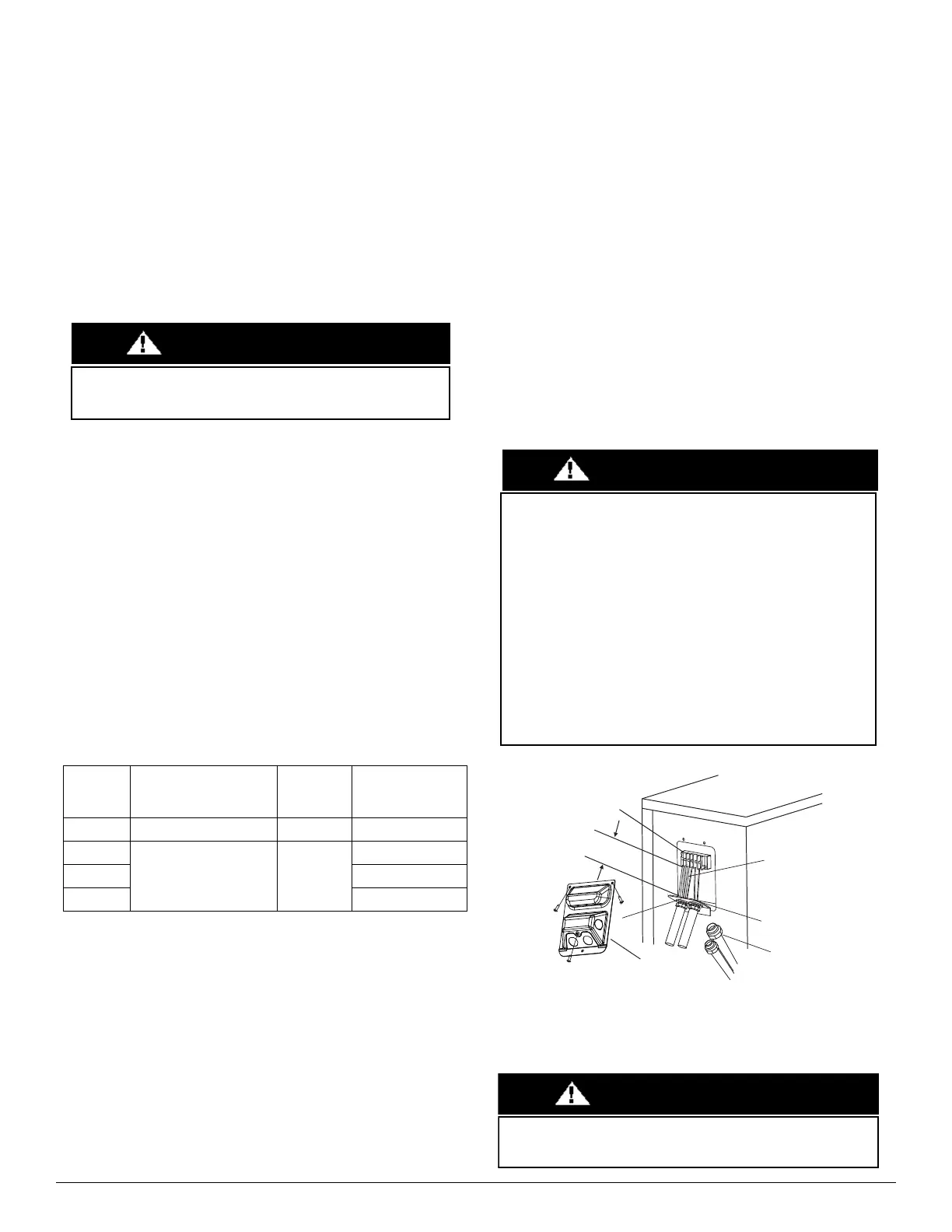
Fig. 19 —Field Wiring
System
Size
Max. Piping Length with no
additional refrigerant
charge per System
Additional
refrigerant
charge
Total Maximum
Piping Length per
system
ft. (m) Oz/ft (g/m) ft. (m)
18K
24.6 (7.5) 0.69 (65)
98 (30)
24K - 30K 164 (50)
36K - 60K 213 (65)
Only use Dry Nitrogen to pressure test refrigerant systems. Use of
other gases can result in injury, property damage or death.
CAUTION
EQUIPMENT DAMAGE HAZARD
Failure to follow this caution may result in equipment damage or
improper operation.
Be sure to comply with local codes while running wire from
indoor unit to outdoor unit.
Every wire must be connected firmly. Loose wiring may cause the
terminal to overheat or result in unit malfunction. A fire hazard
may also exist. Therefore, ensure all wiring is tightly connected.
No wire should be allowed to touch the refrigerant tubing,
compressor or any moving parts.
Disconnecting means must be provided and shall be located
within sight and readily accessible from the air conditioner.
Connecting cable with the conduit shall be routed through hole in
the conduit panel.
CAUTION
Wire Cover
Over 1.57in.(40mm)
Terminal block
Conduit panel
Conduit fitting
Connecting cable
Select the appropriate conduit opening for the
wire size used.
An approved and listed fitting must be used to securely affix
conduit in accordance with NEC and local codes.
WARNING
 Loading...