38MURA: Installation Instructions
Manufacturer reserves the right to change, at any time, specifications and designs without notice and without obligations.
16
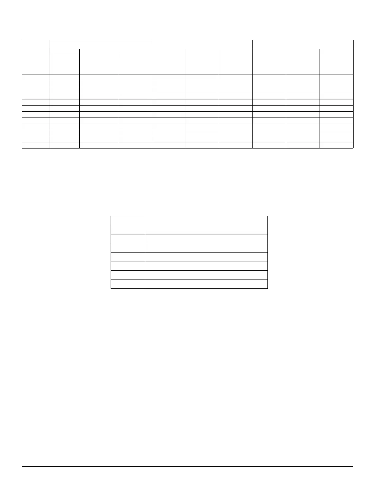
ELECTRICAL DATA
Table 9 — Electrical Data
LEGEND
FLA - Full Load Amps
MCA - Minimum Circuit Amps
MOPA - Maximum Overcurrent Protection Ampacity
24V CONNECTION DIAGRAMS
Table 10 — Terminal Function
NOTE: Terminal D is now energized when the outdoor unit goes into defrost mode and can be used to enable electric heat. This feature is not
available when the outdoor unit communicates with the indoor unit via non-polarity RS485 Communication S1-S2.
OUTDOOR
UNIT
208/230-1-60 COOLING HEATING
Minimum
Circuit
Ampacity
(MCA)
Maximum
Overcurrent
Protection
Ampacity
(MOCP)
MAX-MIN
VOLTAGE
RANGE
Running
Current
Power
Consumption
Power Factor
Running
Current Range
Power
Consumption
Power Factor
18K 16 20 253-187 7.5 1620 97.2 6.7 1510 96.9
18K HH 16 20 253-187 6.5 1430 71.5 7 1550 71.5
24K 19 30 253-187 9.7 2120 98.9 9.8 2150 98.8
24K HH 20.5 35 253-187 9.4 1920 94.6 9.13 2040 94.5
30K 20 35 253-187 12.2 2760 95.8 12.4 2850 96.3
30K HH 23 35 253-187 12.4 2720 96.4 12.5 2780 96.7
36K 24 40 253-187 15.82 3750 97.2 16.12 3496 96.8
36K HH 41 50 253-187 14.8 3300 97.8 14.8 3400 97.6
48K 34 50 253-187 21.9 5046 98 23.3 5373 98.4
48K HH 42 50 253-187 24.2 5530 99 21.5 4880 98.9
60K 34 60 253-187 23.8 5644 98.3 20.9 4959 97.7
60K HH 42 60 253-187 26.7 6110 97.9 21.5 4940 97.1
R 24V Power Connection
C Common
Y1 Low Demand
Y2 High Demand
B Heating Reversing Valve
W Heating Control
D Defrost - (24V output signal)
L System Fault - (24V output signal)
 Loading...