9. Reinstall 2 snap-in clips to correctly position and secure coil
assembly in unit. Be sure clip with large offset is used on right
side of unit to secure horizontal pan.
10. Remove 2 oval coil access panel plugs and reinstall into holes
on left side of coil access panel and fitting panel.
11. Remove insulation knockouts on right side of coil access
panel.
12. Reinstall access and fitting panels, aligning holes with tubing
connections and condensate pan connections. Be sure to
reinstall metal clip between fitting panel and vertical conden-
sate pan.
Make sure liquid and suction tube grommets are in place to prevent
air leaks and cabinet sweating.
DOWNFLOW INSTALLATIONS
To convert units for downflow applications, refer to Installation
Instructions supplied with kit for proper installation. For 40FKA
unit size 003, use kit Part No. KFADC0201SLP. For 40FKA unit
sizes 002, 005, and 006 use kit Part No. KFADC0401ACL. Use
fireproof resilient gasket, 1/8- to 1/4-in. thick, between duct, unit,
and floor.
Step 3—Air Ducts
Connect supply-air duct over outside of 3/4-in. flange provided on
supply-air opening. Secure duct to flange with proper fasteners for
type of duct used, and seal duct-to-unit joint.
Duct connection flanges are provided on unit air discharge
connection.
When using 40FKA units with 18-, 20-, 24-, and 30-kw electric
heaters, maintain a 1-in. clearance from combustible materials to
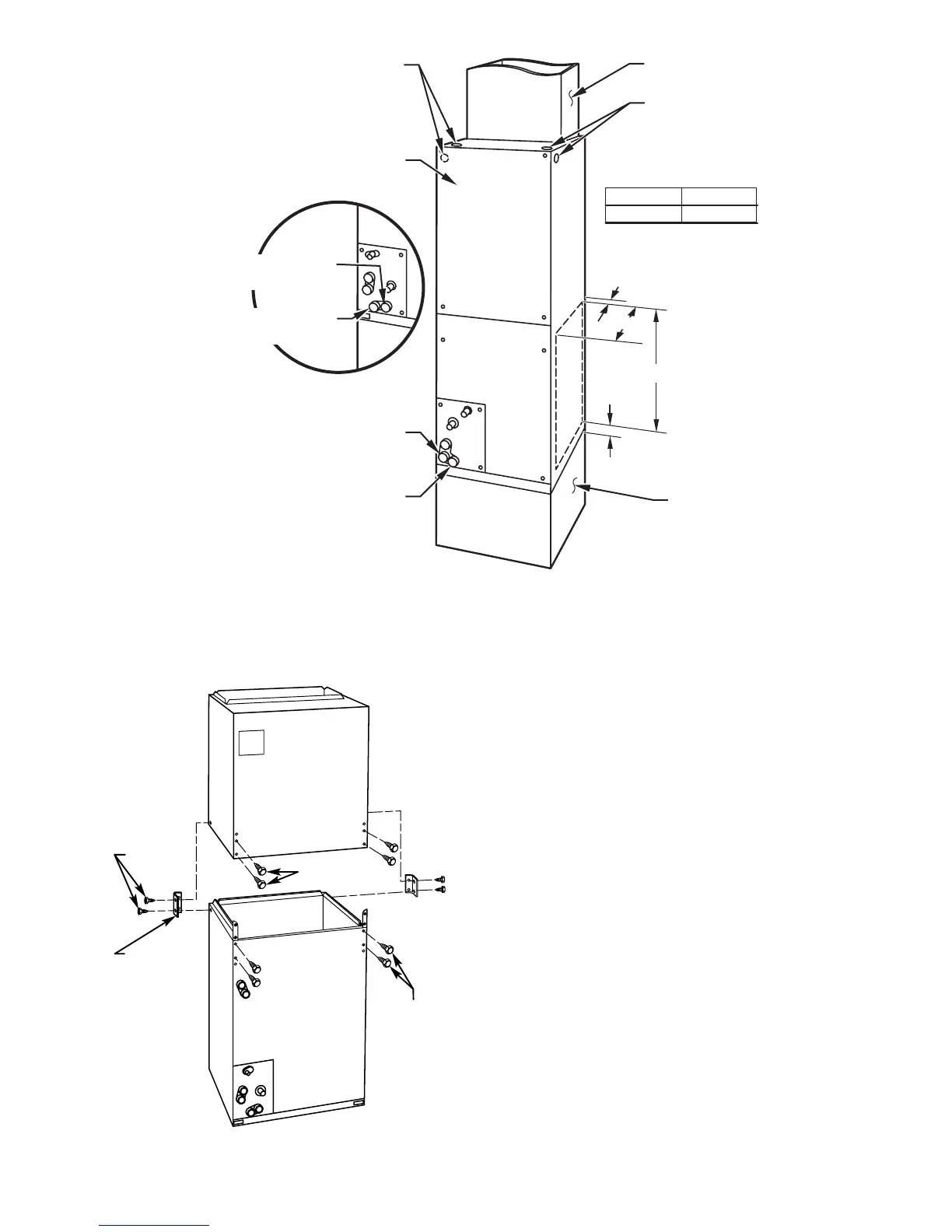
→ Fig. 2—Slope Coil in Upflow Application
A00091
A COIL
UNITS
POWER ENTRY
OPTIONS
LOW VOLT
ENTRY
OPTIONS
FIELD MODIFIED
SIDE RETURN
LOCATION FOR
SLOPE COIL
UNITS ONLY
FIELD SUPPLIED
RETURN PLENUM
UPFLOW/DOWNFLOW
SECONDARY DRAIN
UPFLOW/DOWNFLOW
PRIMARY DRAIN
UNIT
003
A
19 In.
A
1
1
⁄
2
″
2
1
⁄
2
″
19
″
FIELD SUPPLIED
SUPPLY DUCT
24-IN. FRONT SERVICE
CLEARANCE
UPFLOW/DOWNFLOW
SECONDARY DRAIN
UPFLOW/DOWNFLOW
PRIMARY DRAIN
002-005 21-IN.
006
Fig. 3—Modular Unit Assembly
A95293
2 SCREWS
2 SCREWS
REAR CORNER
BRACKET
BLOWER BOX
COIL BOX
2 SCREWS
3
 Loading...