GROUND CONNECTIONS
The cabinet must have an uninterrupted or unbroken ground
according to NEC, ANSI/NFPA 70 and local codes to
minimize personal injury if an electrical fault should occur.
The ground may consist of electrical wire or metal conduit
when installed in accordance with existing electrical codes.
(See Ground/Conduit Note below.) Failure to follow this
warning could result in an electrical shock, fire, or death.
NOTE: Use UL listed conduit and conduit connector to connect
supply wire(s) to unit and obtain proper grounding. If conduit
connection uses reducing washers, a separate ground wire must be
used. Grounding may also be accomplished by using grounding
lug provided in control box. Use of dual or multiple supply circuits
will require grounding of each circuit to ground lugs provided on
unit and heaters.
Step 5—Refrigerant Tubing Connection and Evacuation
This fan coil is supplied with an R-22 TXV factory installed. If
installing as part of a Puron® system, the TXV must be replaced
using a Puron TXV. See outdoor unit literature for correct Puron
TXV Kit number.
See Dimensional Drawing in Product Data for tube connection
sizes, type, and locations. Use accessory tubing package with
insulated suction tube, or field-supplied tubing of refrigerant
grade. Insulate entire suction tube if field-supplied tubing is used.
Do not use damaged, dirty, or contaminated tubing because it may
plug refrigerant flow control device. When tubing package is used
and sweat connections are made within 60 sec, coil and tubing
system does not require evacuation. Always evacuate coil and
field-supplied tubing to 500 microns before opening outdoor unit
service valves.
A brazing shield MUST be used when tubing sets are being
brazed to the unit connections to prevent damage to the unit
surface. Braze with Sil-Fos or Phos-copper on copper to
copper joints. Wrap a wet cloth around rear of fitting to
prevent damage to TXV.
To prevent damage to thermostatic expansion valve, remove
sensor bulb from vapor tube while brazing vapor connections.
Units have sweat suction and liquid tube connections. Make
suction tube connection first.
1. Cut tubing to correct length.
2. Insert tube into sweat connection on unit until it bottoms.
3. Braze with Sil-fos or Phos-copper.
Wrap a wet cloth around rear of fitting to prevent damage to
factory-made joints.
4. Evacuate coil and tubing system if connections are not made
within 60 sec or tubing package is not used.
Step 6—Condensate Drain
Units are equipped with primary and secondary 3/4-in. FPT drain
connections. For proper condensate line installation see Figs. 2, 4,
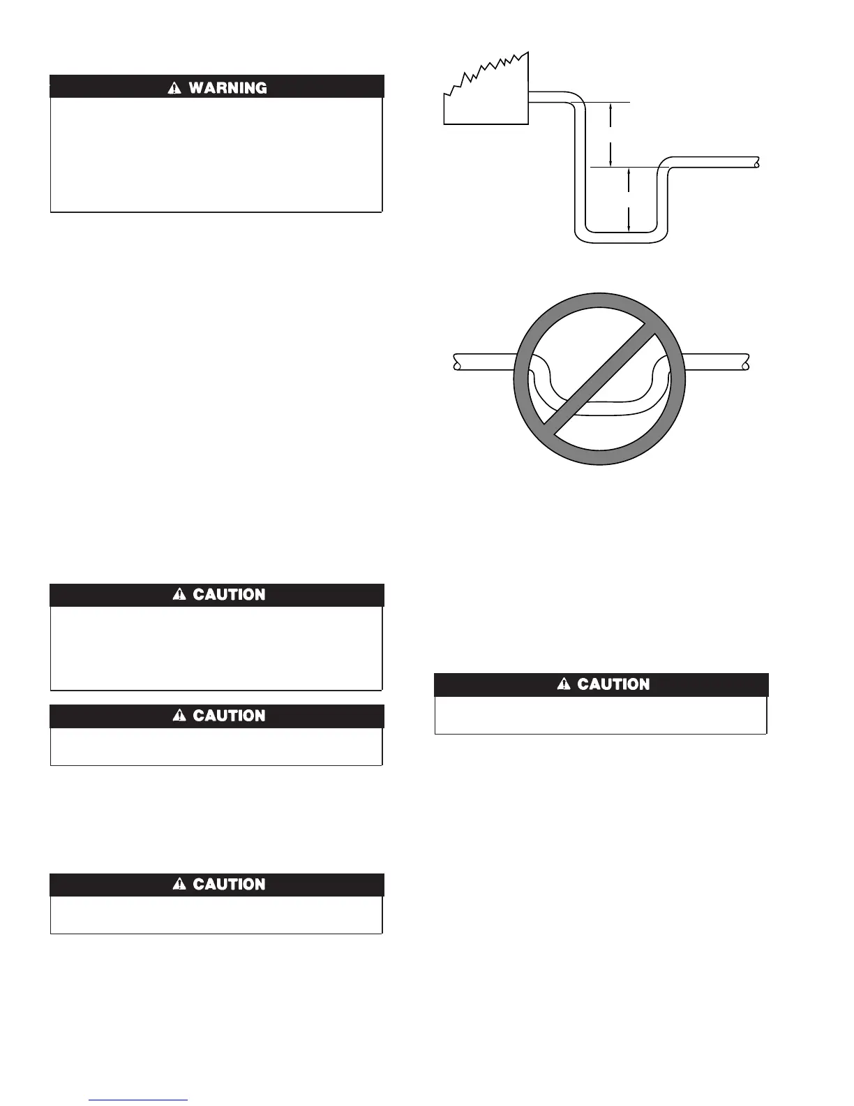
5, 6, and 7. To prevent property damage and achieve optimum
drainage performance, BOTH primary and secondary drain lines
should be installed and include properly sized condensate traps.
(See Fig. 13 and 15.) Factory-approved condensate traps are
available (Kit No. KFAET0125ETK). Be sure to install plastic
push-in plugs in unused condensate drain fittings. It is recom-
mended that PVC fittings be used on the plastic condensate pan.
Do not over-tighten. Finger-tighten plus 1-1/2 turns. Use pipe
dope.
Shallow running traps are inadequate and DO NOT allow
proper condensate drainage. (See Fig. 14.)
NOTE: When connecting condensate drain lines, avoid blocking
filter access panel. Prime both primary and secondary condensate
traps after connecting to drain pan.
NOTE: If unit is located in or above a living space where damage
may result from condensate overflow, a field-supplied external
condensate pan should be installed underneath the entire unit, and
a secondary condensate line (with appropriate trap) should be run
from the unit into the pan. Any condensate in this external
condensate pan should be drained to a noticeable place. As an
alternative to using an external condensate pan, some localities
may allow the use of a separate 3/4-in. condensate line (with
appropriate trap) to a place where the condensate will be notice-
able. The owner of the structure must be informed that when
condensate flows from the secondary drain or external condensate
pan, the unit requires servicing, or water damage will occur.
Install traps in the condensate lines as close to the coil as possible.
(See Fig. 15.) Make sure that the outlet of each trap is below its
connection to the condensate pan to prevent condensate from
overflowing the drain pan. Prime all traps, test for leaks, and
insulate traps if located above a living area.
Fig. 13—Recommended Condensate Trap
A95321
2
1
⁄4″
2
1
⁄4″
UNIT
Fig. 14—Insufficient Condensate Trap
A95320
DO NOT USE SHALLOW RUNNING TRAPS!
8
→
 Loading...