24-V CONTROL SYSTEM CONNECTIONS TO UNIT
PRINTED-CIRCUIT BOARD (PCB)
Refer to unit wiring instructions for recommended wiring proce-
dures. Use No. 18 AWG color-coded, insulated (35°C minimum)
wires to make low-voltage connections between thermostat and
unit. If thermostat is located more than 100 ft from unit (as
measured along the low-voltage wires), use No. 16 AWG color-
coded, insulated (35°C minimum) wires. PCB is circuited for
single-stage heater operation. When additional heater staging is
desired using outdoor thermostats or Intelligent Heat staging,
remove Jumper J2 on PCB to enable staging.
Connect low-voltage leads to thermostat and outdoor unit. (See
Fig. 8, 9, 10, and 11.)
INTELLIGENT HEAT STAGING OPTION
Intelligent Heat staging is an element of the Comfort Heat Pump
System. It requires the use of any one the following electric heat
packages: relay heaters KFCEH1401N09, KFCEH1501F15,
KFCEH1701C15, KFCEH1801F20, KFCEH1901C20,
KFCEH2101F24, OR KFCEH2201F30.
Complete system low-voltage wiring as shown in Figs. 8, 9, 10,
and 11.
NOTE: Where local codes require thermostat wiring be routed
through conduit or raceways, splices can be made inside the fan
coil unit. All wiring must be NEC Class l and must be separated
from incoming power leads.
A factory-authorized disconnect kit is available for installation of
0- through 10-kw applications. When electric heat packages with
circuit breakers are installed, the circuit breaker can be used as a
disconnect.
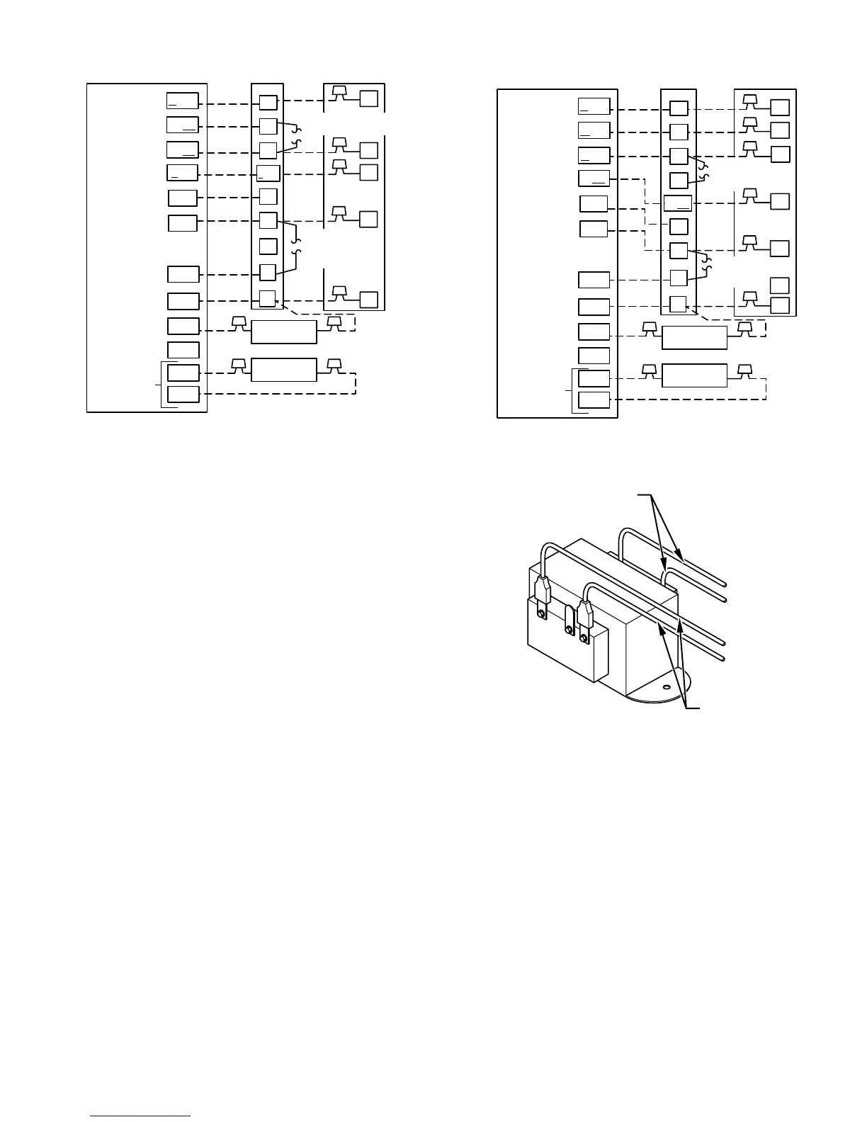
Transformer is factory wired for 230-v operation. For 208-v
applications, disconnect black wire from 230-v terminal on trans-
former and connect it to 208-v terminal. (See Fig. 12.)
The secondary circuit of transformer is protected by a 5-amp fuse
mounted on printed-circuit board.
IMPORTANT: Do not use outdoor thermostat kit with Intelligent
Heat staging.
COMFORT OPTIONS — SUPER COMFORT HEAT AND
SUPER DEHUMIDIFY
Super Comfort Heat and Super Dehumidify options are possible
when the 40FKA Fan Coil is installed with an outdoor temperature
sensor (Super Comfort Heat only) and the factory supplied
Thermidistat™ Control or Comfort Zone II.
Complete the system low voltage wiring as shown in Fig. 8, 9, 10,
and 11.
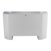
Fig. 10—40FKA Fan Coil with 1—Speed Heat Pump
A98234
O/W2
W/W1
Y1/W2
G
R
O
W2
INDOOR CONTROL
40FKA
FAN COIL
1-SPEED
HEAT PUMP
W1
G
C
Y
R
W2
O
C
DHUM
HUM
B
S1
S2
Y/Y2
R
Y1
C
DH
HEAT STAGE 3
HEAT STAGE 2
HEAT/COOL
STAGE 1
RVS COOLING
FAN
24 VAC HOT
24 VAC COMM
DEHUMIDIFY
HUMIDIFY
RVS HEATING
OUTDOOR
SENSOR
CONNECTION
Y/Y2
HUMIDIFIER
(24 VAC)
OUTDOOR
SENSOR
REMOVE J2 JUMPER
FOR HEAT STAGING
REMOVE
J1 JUMPER FOR
DEHUMIDIFY
MODES
Fig. 11—40FKA Fan Coil with 2—Speed Heat Pump
A98235
O/W2
W/W1
Y1/ W2
G
R
O
Y1
INDOOR CONTROL
40FKA
FAN COIL
2-SPEED
HEAT PUMP
W1
G
W2
C
Y2
R
W3
W2
Y1
O
C
DHUM
HUM
B
S1
S2
Y/Y2
R
C
DH
HEAT/COOL
STAGE 1
HEAT STAGE 3
HEAT/COOL
STAGE 2
RVS COOLING
FAN
24 VAC HOT
24 VAC COMM
DEHUMIDIFY
HUMIDIFY
RVS HEATING
OUTDOOR
SENSOR
CONNECTION
Y/Y2
HUMIDIFIER
(24 VAC)
OUTDOOR
SENSOR
REMOVE J2
JUMPER FOR
HEAT STAGING
REMOVE J1 FOR
DEHUMIDIFY
MODES
Fig. 12—Transformer Connections
A94067
230
C
208
BRN
RED
YEL
BLK
SECONDARY
PRIMARY
7
 Loading...