discharge plenum and ductwork for a distance of 36 in. from unit.
Use accessory downflow base to maintain proper clearance on
downflow installations.
Use flexible connectors between ductwork and unit to prevent
transmission of vibration. When electric heater is installed, use
heat resistant material for flexible connector between ductwork
and unit at discharge connection. Ductwork passing through
unconditioned space must be insulated and covered with vapor
barrier.
DUCTWORK ACOUSTICAL TREATMENT
Metal duct systems that do not have a 90° elbow and 10 ft of main
duct to first branch takeoff may require internal acoustical insula-
tion lining. As an alternative, fibrous ductwork may be used if
constructed and installed in accordance with the latest edition of
SMACNA construction standard on fibrous glass ducts. Both
acoustical lining and fibrous ductwork shall comply with National
Fire Protection Association Standards 90A or B as tested by UL
Standard 181 for Class 1 air ducts.
Step 4—Electrical Connections
On units with a factory installed disconnect with pull-out removed,
service and maintenance can be safely performed on only the load
side of the control package.
Field wires on the line side of the disconnect found in the fan
coil unit remain live, even when the pull-out is removed.
Service and maintenance to incoming wiring can not be
performed until the main disconnect switch (remote to the
unit) is turned off. Failure to do so will result in electrical
shock causing personal injury or death.
LINE-VOLTAGE CONNECTIONS
If unit contains an electric heater, remove and discard power plug
from fan coil and connect male plug from heater to female plug
from unit wiring harness. (See Electric Heater Installation Instruc-
tions.)
For units without electric heat:
1. Connect 208/230v power leads from field disconnect to
yellow and black stripped leads.
2. Connect ground wire to unit ground lug.
NOTE: Units installed without electric heat should have a field-
supplied sheet metal block-off plate covering the heater opening.
This will reduce air leakage and formation of exterior condensa-
tion.
Check all factory wiring per unit wiring diagram and inspect
factory wiring connections to be sure none were loosened in transit
or installation.
Before installing or servicing system, always turn off all
power to system. There may be more than 1 disconnect
switch. Turn off accessory heater power if applicable. Elec-
trical shock can cause personal injury or death.
If a disconnect switch is to be mounted on the unit, select a
location where drill or fastener will not contact electrical or
refrigerant components. Electrical shock can cause personal
injury or death.
NOTE: Before proceeding with electrical connections, make
certain that supply voltage, frequency, and phase are as specified
on unit rating plate. Be sure that electrical service provided by the
utility is sufficient to handle the additional load imposed by this
equipment.
See unit wiring label for proper field high- and low-voltage wiring.
Make all electrical connections in accordance with NEC and any
local codes or ordinances that may apply. Use copper wire only.
The unit must have a separate branch electric circuit with a
field-supplied disconnect switch located within sight from, and
readily accessible from the unit.
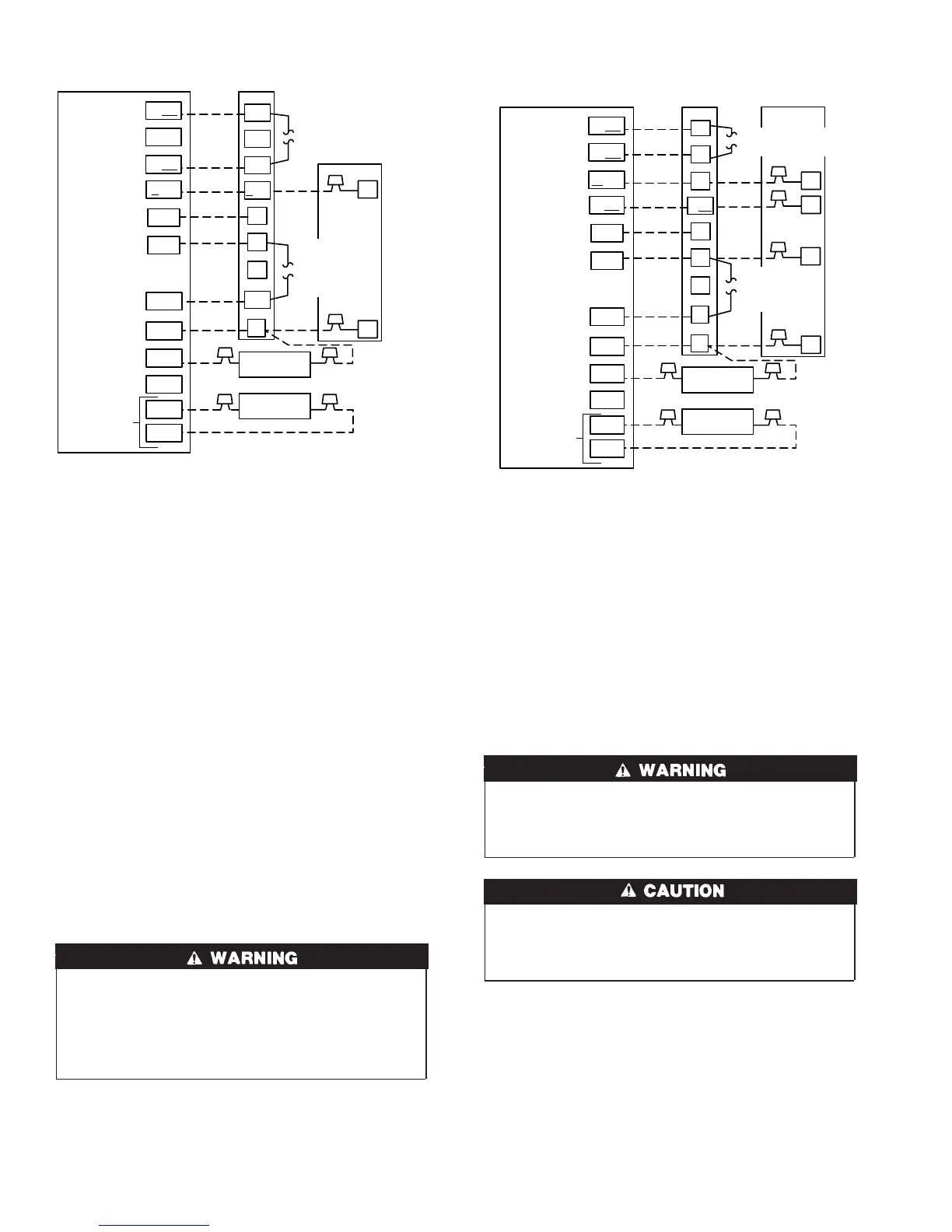
Fig. 8—40FKA Fan Coil with 1-Speed Air Conditioner
A98232
O/W2
Y1/W2
W/W1
G
R
W2
Y1
INDOOR CONTROL
40FKA
FAN COIL
1-SPEED
AIR CONDITIONER
W1
G
C
Y
C
DHUM
HUM
B
S1
S2
Y/Y2
R
O
C
DH
HEAT STAGE 2
N/A
HEAT STAGE 1
COOL STAGE 1
FAN
24 VAC HOT
24 VAC COMM
DEHUMIDIFY
HUMIDIFY
N/A
OUTDOOR
SENSOR
CONNECTION
Y/Y2
HUMIDIFIER
(24 VAC)
OUTDOOR
SENSOR
REMOVE J2 JUMPER
FOR HEAT STAGING
REMOVE
J1 JUMPER
FOR
DEHUMIDIFY
MODES
Fig. 9—40FKA Fan Coil with 2-Speed Air Conditioner
A98233
O/W2
W/W1
Y1/W2
G
R
W2
W1
INDOOR CONTROL
40FKA
FAN COIL
2-SPEED
AIR CONDITIONER
Y1
G
C
Y2
R
Y1
C
DHUM
HUM
B
S1
S2
Y/Y2
R
O
C
DH
HEAT STAGE 2
HEAT STAGE 1
COOL STAGE 1
COOL STAGE 2
FAN
24 VAC HOT
24 VAC COMM
DEHUMIDIFY
HUMIDIFY
N/A
OUTDOOR
SENSOR
CONNECTION
Y/Y2
HUMIDIFIER
(24 VAC)
OUTDOOR
SENSOR
REMOVE J2 JUMPER
FOR HEAT STAGING
REMOVE
J1 JUMPER FOR
DEHUMIDIFY
MODES
6
→
 Loading...