3
English
Legend
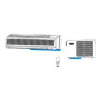
Fan coil units “Hydronic Global Satellite”
Ref. Q.ty
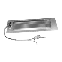
1 Electric heater
1 Thermostat cover
1 Circuit diagram
2 Cover screws
2 Labels
1 Screw for relay
2 Instructions
h 1 Support flange
Fig.1
H Outlet ange
Fig.3
Screw for relay
E Power terminal block
F Multicore faston terminal connector
Z Cable clamp
• WARNING:donotinstallheating
element kit when the unit is
configured
with lateral air outlets or octopus.
• Heatingelementkitcanonlybeinstallediftheunitiscongured
with a front air outlet. Maximum external static pressure is shown
in table 2.
• Readthisinstructionmanualthoroughlybeforeusingthe
heating element kit and keep it for further consultation even after
installation.
• Thiskitcomplieswithlowvoltage(EEC/73/23),electromagnetic
compatibility(EEC/89/336)Directive.
• Theinstallationmustbecarriedoutbyaqualiedinstaller.
• Forsafetyreasons,installersarerequiredtoreadthegeneral
information carefully.
• Followalltheinstructionsbelowtoensuresafety.
• Inspectthekitfordamageduetoimpropertransport.Donot
install or use damaged equipment.
• Topreventre,explosionorinjury,donotoperatetheunit
with kit near dangerous substances or close to naked light
equipment.
• Checkthatvoltageandfrequencyofthemainspowersupplyare
those required for the kit to be installed;
the available power must
be adequate
to operate any other appliances connected to the
same line.
• Makesurethatproperlysizeddisconnectingandsafetyswitches
are installed.
• Themanufacturerdeclinesanyliabilityfordamageresulting
from modifications or errors in the electrical connections. Failure
toobservetheinstallationinstructions,oruseofthekitunder
conditions other than those indicated in the table “Operating
limits”oftheunit/kitinstallationmanual,willimmediately
invalidate the unit warranty.
• AllofthemanufacturingandPackagingmaterialsusedforyour
new appliance are compatible with
the environment and can be
recycled.
• Wheninstallingtheheatingelementkitandafterconnecting
theelectriccables,covertheconnectorsusingtheprotection
devices.
• Inordertoavoidelectricshock,reorinjury,stopthekitand
disconnectthesafetyswitchincaseofabnormalevents(suchas
smellofburning)andcallCarrierServiceforfurtherinstructions.
• WARNING:Disconnectthemainspowersupplypriortoany
maintenance operations or prior to handling any internal parts of
the kit.
• Donotattempttorepair,move,modifyorre-installthekitonyour
own. To avoid electric shock or fire make sure these operations
are carried out by qualified personnel only.
• Contactthequaliedserviceifoneofthefollowingeventstakes
place:
- hot or damaged power supply cable; frequent operation of the
protection devices;
- unusualsmell(suchassmellofburning).
Safety precautions
Installation
Tabel 2
Electric heater operating limit
Max. T of indoor air +27° C
42DWC Maximum outdoor static pressure [Pa]
07 75
09 150
12 170
16 190
•Disconnecttheproductfromthemainspowersupplypriortoinstalling
the kit.
•Loosenthexingscrews(g.1)andremovetheoutletange(ref.H).
•Fix the electric heater to the unit outlet using the screws removed
previously
(g.2a-b).
•Removetheindicatedareafromtheelectricbox(g.2a-b).
•Place
therelayinsidetheelectricboxandxitusingthescrew(g.
3).
•Makeelectricconnectionsasshowninthecircuitdiagram and in
g.3.
-Connectthebluecable(ref.Y)intheelectricboxtocontactA1of
relaycoil(ref.A).
-Connecttheorangecable(ref.X)ofcontactA2oftherelaycoil(ref.
B)toterminal“H”ofthe6poleterminalblock(ref.F).
-Connecttheredcableofthethermostat(ref.K)toterminalLofthe
powerterminalblock(ref.E).
-Connecttheblackcableofthethermostat(ref.G)tocontact11of
therelay(ref.C).
-Connectthebluecableoftheelectricheaters(ref.J)toterminalN
ofthepowerterminalblock(ref.E).
-Connecttheblackcableoftheelectricheaters(ref.I)tocontact14
oftherelay(ref.D).
•Whenconnectionsareallmade,usethecableclamp(ref.Z)toxthe
cablesfromtheelectricheatersasshowning.3.
• Maketheelectricalconnectiontothemainselectricitysupplyusing
the cable indicated in Table 1 and according to the circuit diagram .
• Makecertainthattheconnectiontothemainselectricitysupplyis
made via an omnipolar switch with opening of contacts of at least
3mm.
•Closetheelectricalpanel.
•Applythecharacteristiclabel supplied with the unit near the unit
label.
kit_129H15.indd 3
1-06-2010 16:43:14
 Loading...