GB - 6
42PHW / 42PHQ / 42PHQ...K
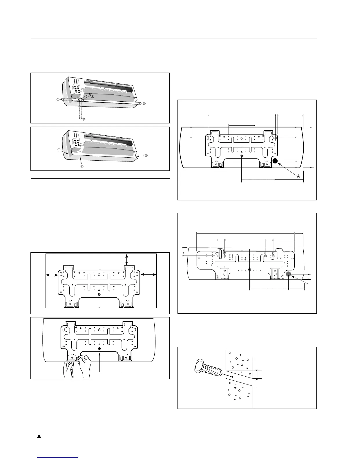
Marking the wall penetration for the
connection piping
Rear piping
• It is best for the piping to go through the wall behind the unit, so
that the unit hides the pipes.
• For this method of installation, make a 65 mm diameter hole in the
wall at point A.
• Drill a 65 mm diameter hole at a slope so that the outside end is
lower (5 - 10 mm) than the inside end.
This will ensure good drainage.
• Cut the wall sleeve to match the wall thickness and pass the pipe
through the hole.
Side or bottom piping
• Remove the knock-out in the unit and pass the pipes through
the wall.
• The pipe should slope downward and away from the unit to
ensure good drainage.
Installation
• The piping can be connected in the four ways indicated by ,
, and .
When the piping is connected to points , or , remove
the knock-out either at the side or at the bottom of the unit.
IMPORTANT NOTE:
This unit has no refrigerant expansion device.
Installing the wall hanging bracket
• Install the wall hanging bracket so that it is level. Use a plumb
line if necessary.
• Be sure to leave the clearance spaces. (Refer to page 3).
• If the wall hanging bracket is not level, water may drip onto the
floor.
• Install the wall hanging bracket with a fixing that is strong
enough to withstand the weight of the unit.
• Before installing the wall hanging bracket, remove it from the unit
by pushing at the indicated parts at the bottom of the body.
• Fasten the wall hanging bracket to the wall with 4 or more screw
anchors through the holes near the outer edge of the bracket.
• Install the wall hanging bracket so that there is no gap between
the bracket and the wall.
• Check that the wall hanging bracket does not move.
This can cause noise during operation.
• If the unit is removed from the wall hanging bracket after installing
it onto the wall, remove it by pushing up the indicated MARKS
(
) at the bottom of the body. (Refer to page 7).
Indoor side
Outdoor side
5 ~ 10 mm lower
Remove screw
42PHW007 - 009 - 012 - 014
42PHQ007 - 007K - 009 - 009K - 012 - 012K - 014 - 014K
42PHW018 - 024
42PHQ018 - 018K - 024 - 024K
Plumb line
300
min.
120 min.
450
min.
450
110
23
245
51
110
56
40
260
180
53
379
899 90
71
71 196
25 53
A
155
350
 Loading...