EasyManua.ls Logo

Carrier 42QH30-H User Manual

Carrier 42QH30-H
22 pages
To Next Page IconTo Next Page
To Previous Page IconTo Previous Page
Page #4 background imageLoading...
Page #4 background image
3
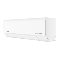
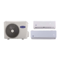
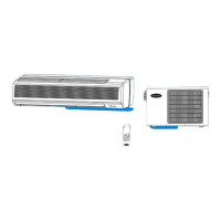
2. SPLIT SYSTEM DESCRIPTION
(a) INDOOR UNIT
x Mounted inside the space to be air-conditioned.
x In summer it filters, dehumidifies and cools air.
x In winter it filters and heats air.
(g) DRAIN HOSE
x Drain the water condensated in the indoor
unit during cooling operation to the outside.
Fig. (1)
HI WALL SPLIT SYSTEMS
53QH-H SERIES HEAT PUMP
53QH-C SERIES COOL ONLY
(e) WIRELESS REMOTE CONTROL (LCD)
Controls on/off, mode, and fan speed,
temperature, timer and swing, and sleep
functions.
(b) OUTDOOR UNIT
x Mounted outside the space to be air-
conditioned.
x It contains compressor, fan, motor, condenser
coil, copper tubing and electrical components.
(
f
) REFRIGERANT PIPING LINES
Insulated copper piping through which refrigerant
R22 flow connects the indoor and outdoor units.
(c) RETURN AIR TO INDOOR UNIT
The return air from the space to be air-conditioned passes
through the front return grille and top the through the anti-
bacteria filters to clean the air from dust and foreign particles
(d) SUPPLY AIR FROM INDOOR UNIT
Cool or warm air comes out of supply
air outlet
Questions and Answers:

Carrier 42QH30-H Specifications

General IconGeneral
BrandCarrier
Model42QH30-H
CategoryAir Conditioner
LanguageEnglish

Summary

1. PRECAUTIONS BEFORE INSTALLATION

SAFETY CONSIDERATIONS

Important safety advice for service and maintenance personnel.

WARRANTY EXCLUSIONS

Details warranty exclusions for misuse, accidents, modifications, and improper installation/maintenance.

2. SPLIT SYSTEM DESCRIPTION

INDOOR UNIT COMPONENTS AND OPERATION

Describes return air, supply air, indoor unit functions, and drain hose.

REMOTE CONTROL AND PIPING

Details remote control functions and refrigerant piping lines.

OUTDOOR UNIT DESCRIPTION

Lists components and location of the outdoor unit.

3. UNIT MODEL DESIGNATION & IDENTIFICATION

MODEL DESIGNATION EXPLANATION

Explains the coding system for unit model designation.

IDENTIFICATION CODES

Defines the codes for Unit Type (Heat Pump/Cool Only).

4. UNIT MODELS & PART NUMBERS

PARTS LIST FOR INDOOR/OUTDOOR UNITS

Lists part numbers and IDs for indoor and outdoor units.

5. SYSTEM OPERATING LIMITS & SAFETY PROTECTIONS

OPERATING TEMPERATURE LIMITS

Specifies max/min indoor/outdoor temps for cooling and heating.

MAIN POWER SUPPLY SPECIFICATIONS

Details nominal, minimum, and maximum voltage requirements.

SYSTEM SAFETY FEATURES AND DEFROST

Lists protection types, activation, and defrost cycle behavior for heat pump systems.

7. EXPLODED VIEW OF INDOOR UNIT

8. PART LIST OF INDOOR UNIT

9. EXPLODED VIEW OF OUTDOOR UNIT

10. PART LIST OF OUTDOOR UNIT

11. WIRING DIAGRAMS

INDOOR UNIT HEAT PUMP WIRING

Shows the wiring connections for the indoor heat pump unit.

INDOOR UNIT COOL ONLY WIRING

Shows the wiring connections for the indoor cool-only unit.

12. OUTDOOR UNIT WIRING DIAGRAMS

OUTDOOR UNIT HEAT PUMP WIRING

Displays the outdoor heat pump unit wiring diagram.

OUTDOOR UNIT COOL ONLY WIRING

Displays the outdoor cool-only unit wiring diagram.

13. FIELD ELECTRICAL CONNECTIONS

HEAT PUMP SYSTEM CONNECTIONS

Illustrates field electrical connections for the heat pump system.

COOL ONLY SYSTEM CONNECTIONS

Illustrates field electrical connections for the cool-only system.

CONNECTION DIAGRAM LEGEND

Explains the numbering and symbols used in the connection diagrams.

14. REFRIGERATION CYCLE

HEAT PUMP SYSTEM REFRIGERANT FLOW

Shows the refrigerant flow for the heat pump system.

15. COOL ONLY REFRIGERATION CYCLE

COOL ONLY SYSTEM REFRIGERANT FLOW

Shows the refrigerant flow for the cool-only system.

16. SELF DIAGNOSTIC FUNCTION

INTRODUCTION TO SELF-DIAGNOSTICS

Introduces the importance of the self-diagnostic function for heat pump systems.

DIAGNOSTIC COMPONENT DETECTION

Lists detected components and their indicator status for malfunctions.

17. AIR FILTER CLEANING

AIR FILTER REMOVAL PROCEDURE

Instructions on how to remove air filters for cleaning.

ACRYLIC-FIBRE FILTER CLEANING

Steps for cleaning acrylic-fiber air filters.

FILTER CLEANING NOTES

Reminders about filter placement and checks after cleaning.

18. PERIODICAL CHECKS

INDOOR UNIT MAINTENANCE SCHEDULE

Lists monthly, 4-monthly, and yearly checks for the indoor unit.

OUTDOOR UNIT MAINTENANCE SCHEDULE

Lists monthly, 4-monthly, and yearly checks for the outdoor unit.

19. TROUBLE SHOOTING

COMPRESSOR & FAN START ISSUES

Addresses issues when the compressor and outdoor fan fail to start.

COMPRESSOR OPERATION PROBLEMS

Deals with overload cycling, continuous operation, and excessive head pressure.

FAN RUNS, COMPRESSOR FAILS

Troubleshoots scenarios where the fan runs but the compressor does not.

20. TROUBLE SHOOTING CONTINUED

PRESSURE RELATED ISSUES

Addresses low head pressure and low/excessive suction pressure.

OUTDOOR FAN & REMOTE CONTROL PROBLEMS

Troubleshoots outdoor fan issues and remote control display/response failures.

21. TROUBLE CHART CONTINUED 1

REMOTE CONTROL FUNCTION ISSUES

Deals with remote control function requests not being acknowledged by the unit.

UNIT START-UP AND COOLING PROBLEMS

Troubleshoots the air conditioner failing to start and insufficient cooling.

22. TROUBLE CHART CONTINUED 2

HEATING AND NOISE/SMELL ISSUES

Addresses insufficient heating, mist, noises, and unpleasant smells.

STARTING MODE AND LED INDICATORS

Explains normal heating start-up and reasons for blinking timer/power LEDs.

Related product manuals