40
ECONOMI$ER SYSTEMS
IMPORTANT: Any economizer that meets the
economizer requirements as laid out in California’s Title
24 mandatory section 120.2 (fault detection and
diagnostics) and/or prescriptive section 140.4 (life−cycle
tests, damper leakage, 5 year warranty, sensor accuracy,
etc), will have a label on the economizer. Any economizer
without this label does not meet California’s Title 24. The
five year limited parts warranty referred to in section
140.4 only applies to factory installed economizers. Please
refer to your economizer on your unit.
The 50TC units may be equipped with a factory−installed
or accessory (field−installed) EconoMi$er system. Two
types are available: with a logic control system
(EconoMi$er IV) and without a control system
(EconoMi$er2). See Fig. 45 for component locations on
each type. See Figs. 46 and 47 for EconoMi$er section
wiring diagrams. Both EconoMi$ers use direct−drive
damper actuators.
CTUATOR
WIRING
HARNESS
ECONOMIER IV
CONTROLLER
OUTSIDE AIR
TEMPERATURE SENSOR
LOW AMBIENT
SENSOR
C06021
ECONOMI$ER2
PLUG
BAROMETRIC
RELIEF
DAMPER
OUTDOOR
AIR HOOD
HOOD
SHIPPING
BRACKET
GEAR DRIVEN
DAMPER
C06022
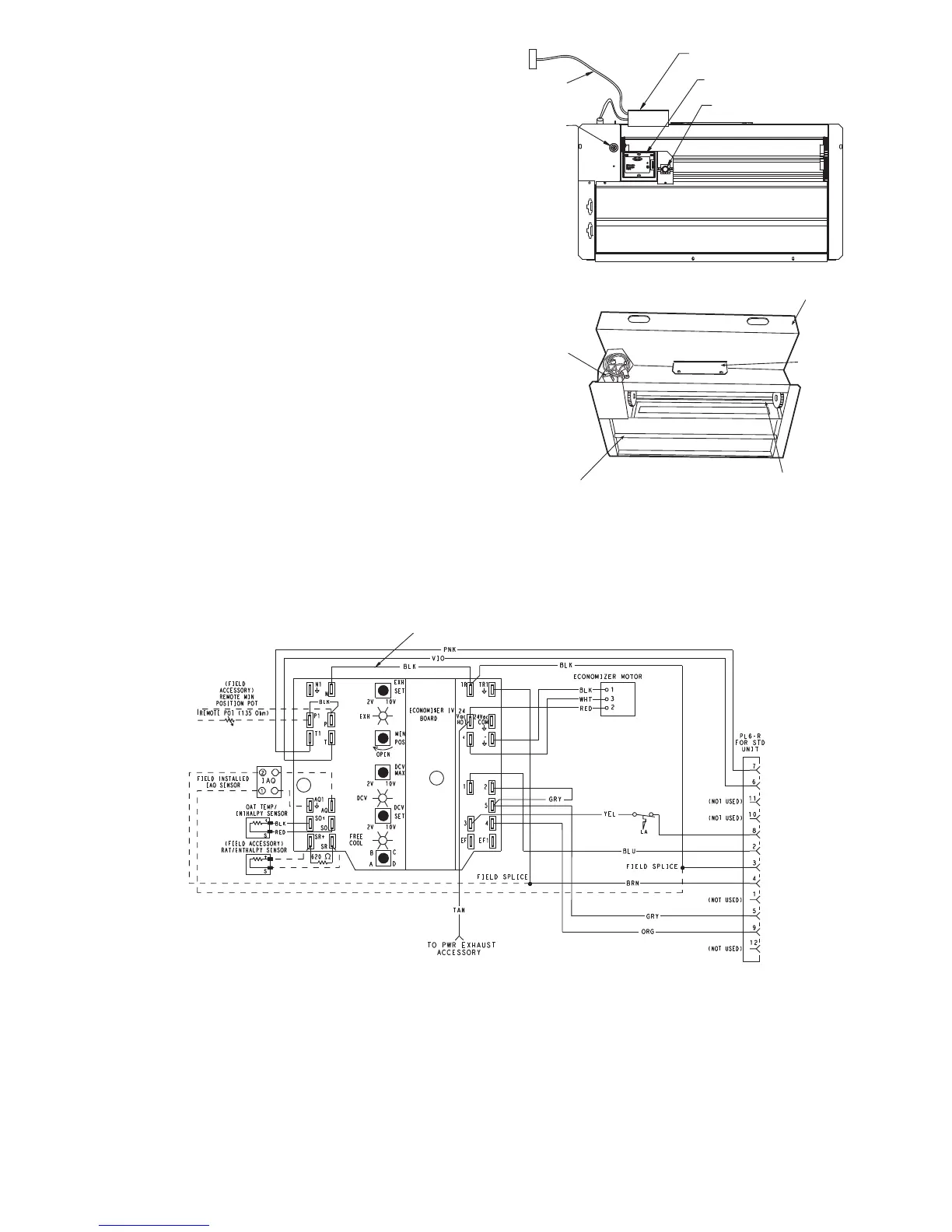
Fig. 45 − EconoMi$er IV Component Locations
FOR OCCUPANCY CONTROL
REPLACE JUMPER WITH
FIELD-SUPPLIED TIME CLOCK
LEGEND
DCV— Demand Controlled Ventilation
IAQ — Indoor Air Quality
LA — Low Ambient Lockout Device
OAT — Outdoor-Air Temperature
POT — Potentiometer
RAT — Return-Air Temperature
Potentiometer Defaults Settings:
Power Exhaust Middle
Minimum Pos. Fully Closed
DCV Max. Middle
DCV Set Middle
Enthalpy C Setting
NOTES:
1. 620 ohm, 1 watt 5% resistor should be removed only when using differential
enthalpy or dry bulb.
2. If a separate field-supplied 24 v transformer is used for the IAQ sensor power
supply, it cannot have the secondary of the transformer grounded.
3. For field-installed remote minimum position POT, remove black wire jumper
between P and P1 and set control minimum position POT to the minimum
position.
8
7
C06028
Fig. 46 − EconoMi$er IV Wiring
 Loading...


