7
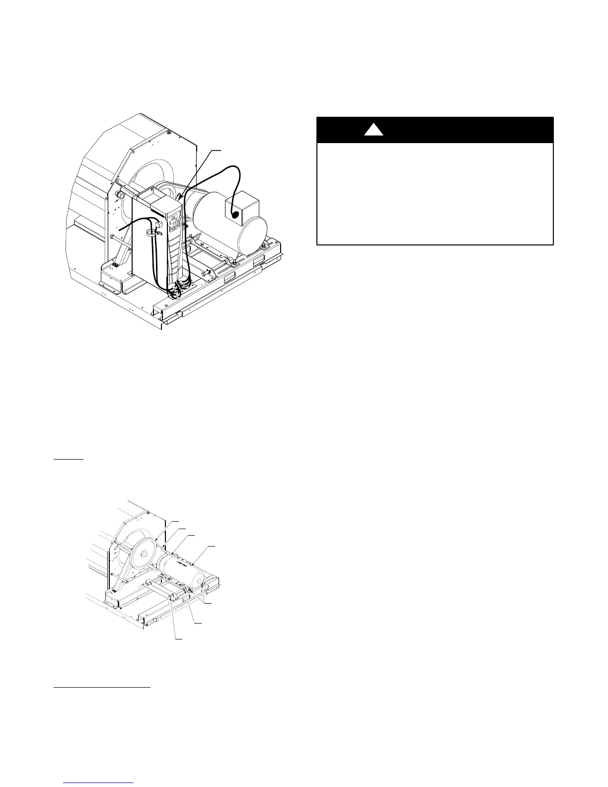
NOTE: The Remote VFD Keypad is a field-installed op
tion. It is not included as part of the Factory installed VFD
option. See “Variable Frequency Drive (VFD) Installa
tion, Setup and Troubleshooting Supplement” for wiring
schematics and performance charts and configuration. See
Fig. 9 for location of the (VFD) as mounted on the various
50HC models.
Variable
Frequency
Drive (VFD)
C11531
Fig. 9 − VFD Location for 50HC 15–27.5 Units
ADDITIONAL VFD INSTALLATION
AND TROUBLESHOOTING
Additional installation, wiring and troubleshooting infor
mation for the VFD can be found in the following manu
als: “Variable Frequency Drive (VFD) Installation, Setup
and Troubleshooting Supplement.”
Motor
When replacing the motor, use the following steps. See
Fig. 10.
BLOWER PULLEY
V-BELT
MOTOR PULLEY
MOTOR
MOTOR MOUNTING
BOLTS (4)
JACK BOLT
JAM NUT (2)
JACK BOLT (2)
C12034
Fig. 10 − Replacing Belt Driven Motor
Replacing the Motor
1. Turn off all electrical power to the unit. Use approved
lockout/tagout procedures on all electrical power
sources.
2. Remove the cover on the motor connection box.
3. Disconnect all electrical leads to the motor.
4. Loosen the two jack bolt jamnuts on the motor
mounting bracket.
5. Turn the two jack bolts counterclockwise until the
motor assembly moves closer to the blower pulley.
6. Remove the V-belt from the blower pulley and motor
pulley.
EQUIPMENT DAMAGE HAZARD
Failure to follow this CAUTION can result in
premature wear and damage to equipment.
Do not use a screwdriver or pry−bar to place the new
V−belt in the pulley groove. This can cause stress on
the V−belt and the pulley, resulting in premature wear
on the V−belt and damage to the pulley.
CAUTION
!
7. Loosen the four mounting bracket bolts and lock
washers.
8. Remove four bolts, four flat washers, four lock wash
ers and four nuts attaching the motor mounting plate
to the unit. Discard all lock washers.
9. Remove the motor and motor mounting bracket from
the unit.
10. Remove four bolts, flat washers, lock washers and
single external-tooth lock washer attaching the motor
to the motor mounting plate. Discard all lock washers
and external-tooth lock washer.
11. Lift the motor from the motor mounting plate and set
aside.
12. Slide the motor mounting band from the old motor.
13. Slide the motor mounting band onto the new motor
and set the motor onto the motor mounting plate.
14. Remove the variable pitch pulley from the old motor
and attach it to the new motor.
15. Inspect the variable pitch pulley for cracks and wear.
Replace the pulley if necessary.
16. Secure the pulley to the motor by tightening the pul
ley setscrew to the motor shaft.
17. Insert four bolts and flat washers through the mount
ing holes on the motor and into holes on the motor
mounting plate.
18. On one bolt, place a new external-tooth lock washer
between the motor and motor mounting band.
19. Make sure the teeth of the external-tooth lock washer
make contact with the painted base of the motor. This
washer is essential for properly grounding the motor.
20. Install four new lock washers and four nuts on the
bolts on the bottom of the motor mounting plate, but
do not tighten the mounting bolts at this time.
21. Set the new motor and motor mounting bracket back
onto the unit. See Fig. 10.
22. Install four bolts, four flat washers, four new lock
washers and four nuts attaching the motor assembly
to the unit, but do not tighten the mounting bolts at
this time.
 Loading...


