10
WALL THERMOSTAT INTERFACE
The standard wall thermostat interface provides a
simple to install thermostat connection. The unit has
a removable terminal connector to make field wiring
easy. See more info on wall thermostat connections
in the Dimensional Drawings and Installation Data
Section.
Notes:
— Thermostat wire i s field supplied and
recommended wire size is 18 to 20 gage
solid thermostat wire.
— Wire s hould never be routed through the
wall sleeve.
— It is recommended to include extra wires
in case a wire breaks or is cut during
installation.
— The thermostat is ordered separately and
a Carrier PTAC approved thermostat is
recommended, see the accessory chart in
the back.
EM (ENERGY MANAGEMENT)
INTERFACE
The EM interface is standard and provides a simple to
install, Energy Management connection. The unit has
a removable terminal connector to make field wiring
easy. When 24VAC is supplied to the input (the EM
connection), the unit will turn off. Once the 24VAC is
removed (becomes 0 volts), the unit will turn back
on.
Note: F or more info, see the section in the back,
Typical Wiring Schematic For Energy
Manag emen t In t erface.
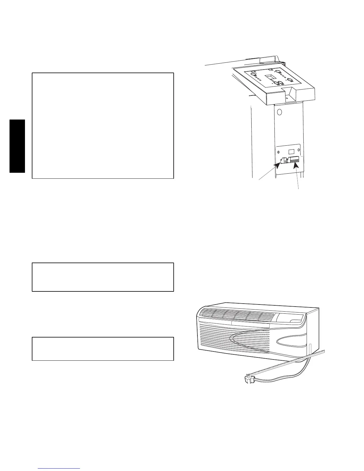
Wall Thermostat
Terminal Connections
Energy Management
Terminal Connections
A07634
Wall Thermostat and Energy Management
Interface
POWER CORD FOR 265V UNITS
The 265v power cord extends 15 --in. from bottom of
front panel and, per UL and National Electric Codes
(NEC), must plug into an electrical subbase.
Note: Accessory power cord and electrical
subbase sold separately. (See Accessory section
in back of this document.)
2
0
1
9
1
8
1
7
1
6
1
5
1
4
1
3
1
2
1
1
1
0
9
8
7
6
5
4
3
2
1
A07635
265V Power Cor d
52M
 Loading...