OPERATING CONTROLS
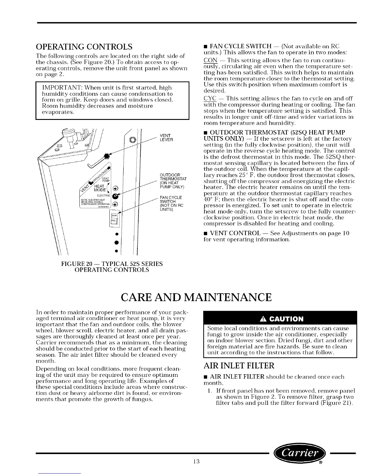
The following controls are located on the right side of
the chassis. (See Figure 20.) To obtain access to op-
erating controls, remove the unit fl'ont panel as shown
on page 2.
IMPORTANT: When unit is first started, high
humidity conditions can cause condensation to
form on grille. Keep doors and windows closed.
Room humidity decreases and moisture
evaporates.
!o/>VE ,
LEVER
_TII T
FIGURE 20 -- TYPICAL 52S SERIES
OPERATING CONTROLS
• FAN CYCLE SWITCH -- (Not available on RC
units.) This allows the fan to operate in two modes:
CON -- This setting allows the fan to run continu-
ously, circulating air even when the temperature set-
ting has been satisfied. This switch helps to maintain
the room temperature closer to the thermostat setting.
Use this switch position when maximum comfort is
desired.
CYC -- This setting allows the fan to cycle on and off
with the compressor du ring heating or cooling. The fan
stops when the temperature setting is satisfied. This
results in longer unit off-time and wider variations in
room temperature and humidity.
• OUTDOOR THERMOSTAT (52SQ HEAT PUMP
UNITS ONLY) -- If the setscrew is left at the factory
setting (in the flflly clockwise position), the unit will
operate in the reverse cycle heating mode. The control
is the defi'ost thermostat in this mode. The 52SQ ther-
mostat sensing capillary is located between the fins of
the outdoor coil. When the temperature at the capil-
lary reaches 25 ° F, the outdoor fi'ost thermostat closes,
shutting off the compressor and energizing the electric
heater. The electric heater remains on until the tem-
perature at the outdoor thermostat capillary reaches
40 ° F; then the electric heater is shut off and the com-
pressor is energized. To set unit to operate in electric
heat mode only, turn the setscrew to the flflly counter-
clockwise position. Once in electric heat mode, the
compressor is disabled for heating and cooling.
• VENT CONTROL See Adjustments on page 10
for vent operating infl)rmation.
CARE AND MAINTENANCE
In order to maintain proper performance of your pack-
aged terminal air conditioner or heat pump, it is very
important that the fan and outdoor coils, the blower
wheel, blower scroll, electric heater, and all drain pas-
sages are thoroughly cleaned at least once per year.
Carrier recommends that as a minimum, the cleaning
should be conducted prior to the start of each heating
season. The air inlet filter should be cleaned every
month.
Depending on local conditions, more fi'equent clean-
ing of the unit may be required to ensure optimum
performance and long operating life. Examples of
these special conditions include areas where construc-
tion dust or heavy airborne dirt is found, or environ-
ments that promote the growth of flmgus.
Some local conditions and environments can cause
flmgi to grow inside the air conditioner, especially
on indoor blower section. Dried flmgi, dirt and other
foreign material are fire hazards. Be sure to clean
unit according to the instructions that follow.
AIR INLET FILTER
• AIR INLET FILTER should be cleaned once each
month.
1. If fi'ont panel has not been removed, remove panel
as shown in Figure 2. To remove filter, grasp two
filter tabs and pull the filter forward (Figure 21).
13
O m
 Loading...