ACCESSORY INSTALLATION
IMPORTANT: Only trained, qualified personnel
and service mechanics should install electrical
accessories on Carrier 52S series products per
Carrier's installation instructions. Please contact
your local electrical contractor, dealer, or distribu-
tor for assistance.
• INSTALL ACCESSORY HARDWIRE KIT OR 265-v
ACCESSORY CORD-CONNECTED KIT -- Install
Carrier accessory hardwire kit according to the
instructions provided with the accessory. The acces-
sory cord-connected kit is for 265-v units only, and
requires an accessory subbase, Part No. SUBBASE,
with a field-installed receptacle.
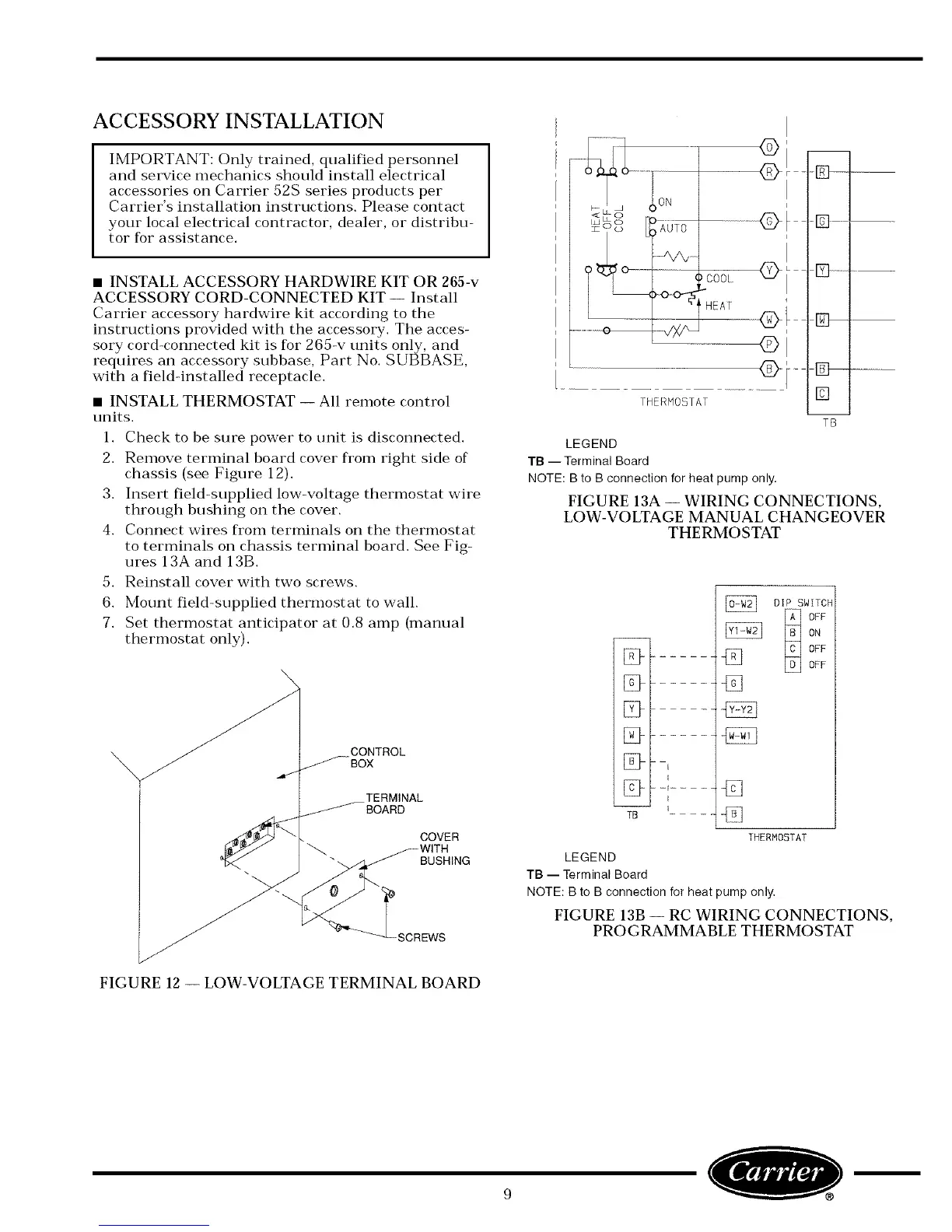
• INSTALL THERMOSTAT -- All remote control
units.
1. Check to be sure power to unit is disconnected.
2. Remove terminal board cover fl'om right side of
chassis (see Figure 12).
3. Insert field-supplied low-voltage thermostat wire
through bushing on the cover.
4. Connect wires from terminals on the thermostat
to terminals on chassis terminal board. See Fig-
ures 13A and 13B.
5. Reinstall cover with two screws.
6. Mount field-supplied thermostat to wall.
7. Set thermostat anticipator at 0.8 amp (manual
thermostat only).
CONTROL
_-BOX
TERMINAL
_BOARD
COVER
BUSHING
SCREWS
/ ion
i
THERMOSTAT
-B]--
.....
[]
TB
LEGEND
TB -- Terminal Board
NOTE: B to B connection for heat pump only.
FIGURE 13A -- WIRING CONNECTIONS,
LOW-VOLTAGE MANUAL CHANGEOVER
THERMOSTAT
TB
---[
I
[
L __
DIP SWITCH
_ FF
ON
OFF
OFF
THERMOSTAT
LEGEND
TB -- Terminal Board
NOTE: B to B connection for heat pump only,
FIGURE 13B -- RC WIRING CONNECTIONS,
PROGRAMMABLE THERMOSTAT
FIGURE 12 -- LOW-VOLTAGE TERMINAL BOARD
O l
 Loading...