52S
SERIES
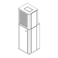
3. See Figure 10 for typical deep wall application.
Inspect accessory outdoor grilles.
IMPORTANT: Be sure that the loam strips and/or
baffles provide a good seal between the grille and
condenser coil tube sheets. These loam strips or
baffles provide a barrier to separate condenser air
from the major components (compressor and fan
motor).
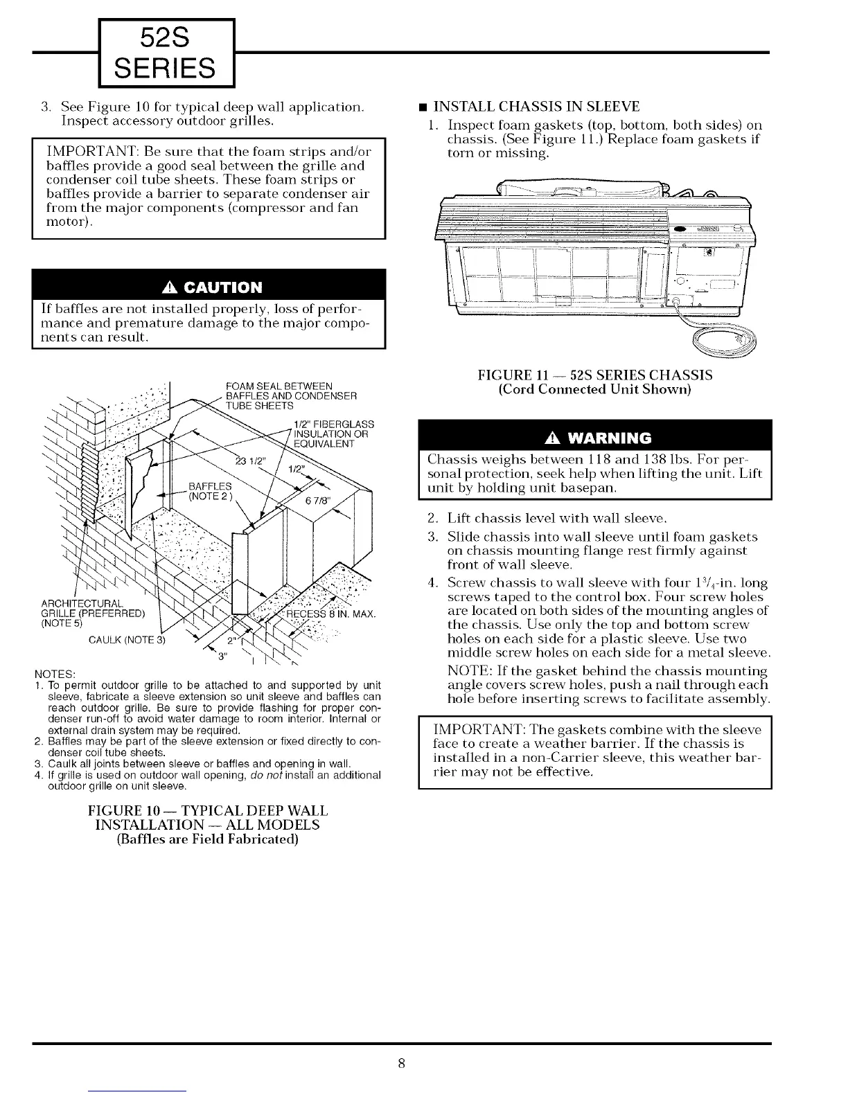
• INSTALL CHASSIS IN SLEEVE
1. Inspect loam gaskets (top, bottom, both sides) on
chassis. (See Figure 11.) Replace foam gaskets if
torn or missing.
If baffles are not installed properly, loss of perfor-
mance and premature damage to the major compo-
nents can result.
FOAM SEAL BETWEEN
CONDENSER
TUBESHEETS
112" FIBERGLASS
ARCHITECTURAL
GRILLE (PREFERRED)
(NOTE 5)
CAULK (NOTE 3)
NOTES:
'.RECESS 8IN. MAX.
1. To permit outdoor grille to be attached to and supported by unit
sleeve, fabricate a sleeve extension so unit sleeve and baffles can
reach outdoor grille. Be sure to provide flashing for proper con-
denser run-off to avoid water damage to room interior. Internal or
external drain system may be required.
2. Baffles may be part of the sleeve extension or fixed directly to con-
denser coil tube sheets.
3. Caulk all joints between sleeve or baffles and opening in wall.
4. If grille is used on outdoor wall opening, do not install an additional
outdoor grille on unit sleeve.
FIGURE 10 -- TYPICAL DEEP WALL
INSTALLATION -- ALL MODELS
(Baffles are Field Fabricated)
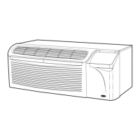
FIGURE 11 -- 52S SERIES CHASSIS
(Cord Connected Unit Shown)
Chassis weighs between 118 and 138 lbs. For per-
sonal protection, seek help when lifting the unit. Lift
unit by holding unit basepan.
2.
3.
4.
Lift chassis level with wall sleeve.
Slide chassis into wall sleeve until foam gaskets
on chassis mounting flange rest firmly against
fl'ont of wall sleeve.
Screw chassis to wall sleeve with four 13/_-in. long
screws taped to the control box. Four screw holes
are located on both sides of the mounting angles of
the chassis. Use only the top and bottom screw
holes on each side for a plastic sleeve. Use two
middle screw holes on each side for a metal sleeve.
NOTE: If the gasket behind the chassis mounting
angle covers screw holes, push a nail through each
hole before inserting screws to facilitate assembly.
IMPORTANT: The gaskets combine with the sleeve
face to create a weather barrier. If the chassis is
installed in a non-Carrier sleeve, this weather bar-
rier may not be effective.
 Loading...