After fully assembling the vent connector to the furnace flue collar,
securely fasten the vent connector to the collar with 2 field-
supplied, corrosion-resistant, sheet metal screws located 180
degrees apart and midway up the collar.
The horizontal portion of the venting system shall maintain a
minimum of 1/4-in. upward slope per linear ft and it shall be
rigidly supported every 5 ft or less with hangers or straps to ensure
that there will be no movement after installation.
Step 9—Start-Up, Adjustment, and Safety Check
GENERAL
The furnace must have a 115-v power supply properly connected
and grounded. Correct polarity must be maintained to enable gas
heating operation.
The gas service pressure must not exceed 0.5 psig (14-in. wc), and
be no less than 0.16 psig (4.5-in. wc).
Thermostat wire connections at R and W/W1 are the minimum
required for gas heating operation. W2 must be connected for
2-stage heating thermostats. C
OM, Y/Y2, and G are required for
cooling, heat pumps, and some other thermostats. Follow manu-
facturer’s instructions supplied with thermostat. These must be
made at 24-v terminal block on control. (See Fig. 10.)
This furnace can be installed with either single-stage heating or
2-stage heating thermostat.
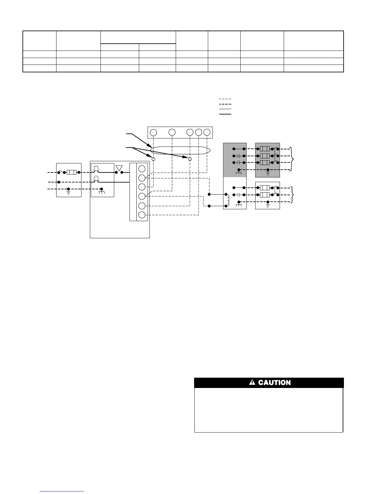
For single-stage thermostats, connect thermostat W to W/W1 at
furnace control terminal block. (See Fig. 11.) For single-stage
thermostats the control determines, based on length of previous
heating on and off cycles, when to operate in low- and high-gas
heat for optimum comfort. Setup Switch-2 (SW-2) must be in the
factory-shipped OFF position. See Fig. 13 and Tables 6 and 7 for
setup switch information.
If 2-stage heating thermostat is to be used, move SW-2 to ON
position at end of furnace installation. This overrides built-in
control process for selecting high and low stage and allows 2-stage
thermostat to select gas heating modes. The W2 from thermostat
must be connected to W2 on furnace control terminal block. (See
Fig. 12.)
Before operating furnace, check each manual reset switch for
continuity. If necessary, press and release button to reset switch.
This furnace is equipped with 2 manual reset limit switches in
gas control area. The switches will open and shut off power
to gas valve if a flame rollout or an overheating condition
occurs in gas control area. DO NOT bypass switches. Correct
inadequate combustion air supply, component failure, re-
stricted flue gas passageway before resetting switches.
SEQUENCE OF OPERATION
Using the schematic diagram follow sequence of operation through
different modes. (See Fig. 14.) Read and follow wiring diagram
very carefully.
Table 5—Electrical Data
UNIT
SIZE
VOLTS—
HERTZ—
PHASE
OPERATING
VOLTAGE RANGE
MAX
UNIT
AMPS
MIN
WIRE
GAGE
MAX WIRE
LENGTH
FT‡
MAXIMUM
FUSE OR
CKT BKR AMPS†
Max* Min*
060-12 115—60—1 127 104 10.5 14 35 15
080-16 115—60—1 127 104 14.2 14 26 15
100-20 115—60—1 127 104 17.9 12 32 20
* Permissible limits of the voltage range at which the unit will operate satisfactorily.
† Time-delay fuse is recommended.
‡ Length shown is as measured 1 way along wire path between unit and service panel for maximum 2 percent voltage drop.
Fig. 11—Heating and Cooling Application Diagram With 1-Stage Thermostat and 1-Stage Condensing Unit
A97443
115-V FUSED
DISCONNECT
SWITCH
(WHEN REQUIRED)
JUNCTION
BOX
CONTROL
BOX
24-V
TERMINAL
BLOCK
TWO-WIRE
HEATING-
ONLY
FIVE
WIRE
1-STAGE THERMOSTAT TERMINALS
FIELD-SUPPLIED
FUSED DISCONNECT
CONDENSING
UNIT
FURNACE
COM
R
WYRG
C
GND
GND
FIELD 24-V WIRING
FIELD 115-, 208/230-, 460-V WIRING
FACTORY 24-V WIRING
FACTORY 115-V WIRING
208/230- OR
460-V
THREE
PHASE
208/230-V
SINGLE
PHASE
WHT
BLK
WHT
BLK
W/W1
W2
Y/Y2
G
NOTES: 1. Connect Y-terminal as shown for proper operation.
2. Some thermostats require a "C" terminal connection as shown.
3. If any of the original wire, as supplied, must be replaced,
use same type or equivalent wire.
10
 Loading...