26
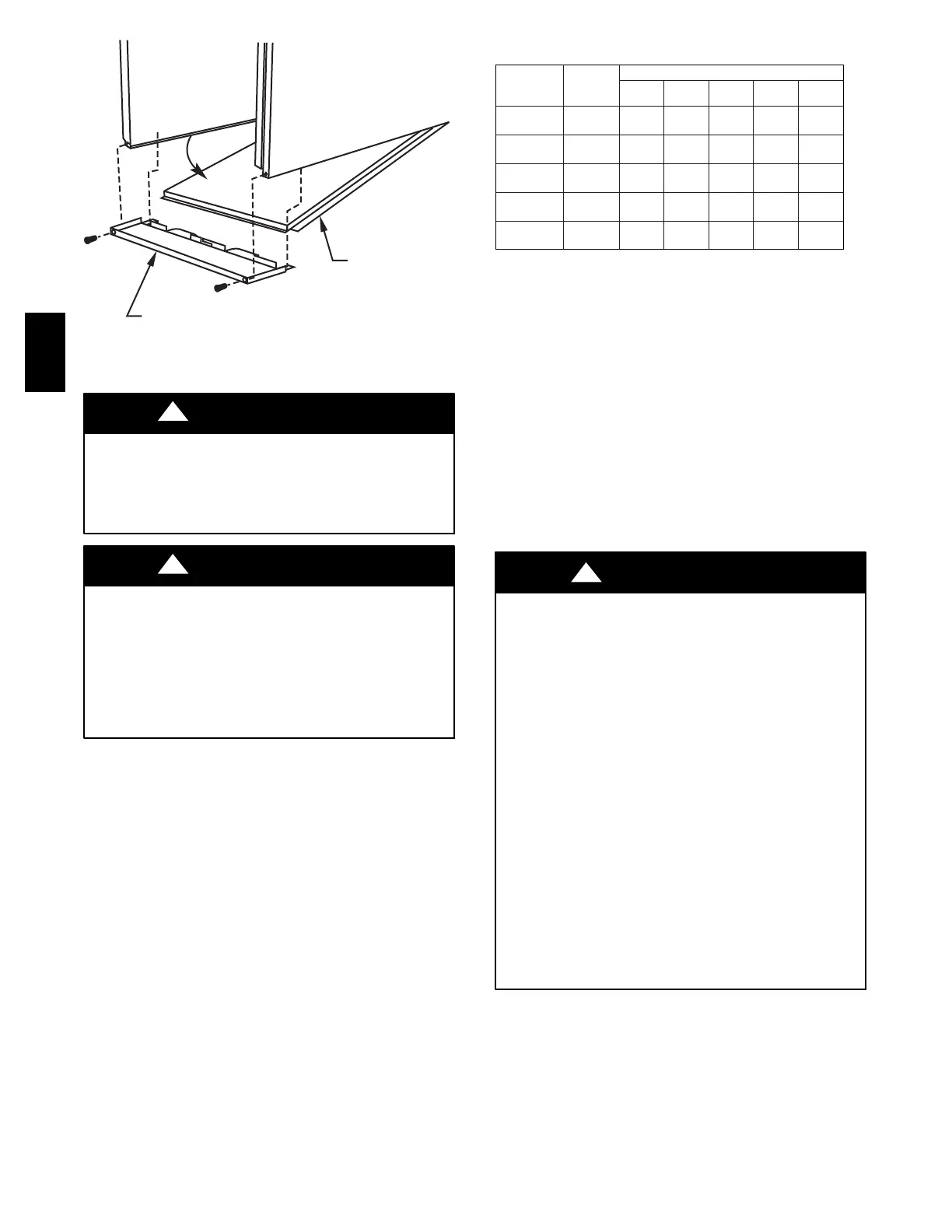
BOTTOM
CLOSURE
PANEL
FRONT FILLER
PANEL
A93047
Fig. 28 -- Removing Bottom Closure Panel
CUT HAZARD
Failure to follow this caution may result in personal injury.
Use care when cutting support rods in filters to protect against
flying pieces and sharp rod ends. Wear safety glasses, gloves,
and appropriate protective clothing.
CAUTION
!
UNIT MAY NOT OPERATE
Failure to follow this caution may result in intermittent unit
operation.
For airflow requirements above 1800 CFM, see Air Delivery
table in Product Data literature for specific use of single side
inlets. The use of both side inlets, a combination of 1 side and
the bottom, or the bottom only will ensure adequate return air
openings for airflow requirements above 1800 CFM.
CAUTION
!
NOTE: Side return-air openings can ONLY be used in
UPFLOW configurations. Install filter(s) as shown in Fig. 26.
Bottom return-air opening may be used with all 4 orientations.
Filter may need to be cut to fit some furnace widths. Install filter
as shown in Fig. 27.
NOTE: Remove and discard bottom closure panel when bottom
inlet is used.
Step 6 -- Bottom Closure Panel
This furnace is shipped with bottom closure panel installed in
bottom return-air opening. This panel MUST be in place when
side return air is used.
To remove bottom closure panel, perform the following:
1. Tilt or raise furnace and remove 2 screws holding front
filler panel. (See Fig. 28.)
2. Rotate front filler panel downward to release holding tabs.
3. Remove bottom closure panel.
4. Reinstall front filler panel and screws.
Table 5 – Maximum Capacity of Pipe*
NOMINAL
IRON PIPE
SIZE
IN. (MM)
INTERN
AL
DIA.
IN. (MM)
LENGTH OF PIPE --- FT (M)
10
(3.0)
20
(6.0)
30
(9.1)
40
(12.1)
50
(15.2)
1/2 (12.7)
0.622
(158)
175 120 97 82 73
3/4 (19.0)
0.824
(20.9)
360 250 200 170 151
1 (25.4)
1.049
(26.6)
680 465 375 320 285
1 --- 1 / 4
(31.8)
1.380
(35.0)
1400 950 770 660 580
1 --- 1 / 2
(38.1)
1.610
(40.9)
2100 1460 1180 990 900
*Cubicftofgasperhr.forgaspressuresof0.5psig(14–IN.WC)orless
and a pressure drop of 0.5-in wc (based on a 0.60 specific gravity gas). Ref:
Table 5 and the NFGC.
Step 7 -- Gas Piping
Gas piping must be installed in accordance with national and
local codes. Refer to current edition of NFGC in the
United States.
Canadian installations must be made in accordance with
NSCNGPIC and all authorities having jurisdiction.
Gas supply line should be a separate line running directly from
meter to furnace, if possible. Refer to Table 5 for recommended
gas pipe sizing.
Risers must be used to connect to furnace and to meter. Support
all gas piping with appropriate straps, hangers, etc. Use a
minimum of 1 hanger every 6 ft (1.8 M). Joint compound (pipe
dope) should be applied sparingly and only to male threads of
joints. Pipe dope must be resistant to propane gas.
FIRE OR EXPLOSION HAZARD
Failure to follow this warning could result in personal injury,
death or property damage.
--Connect gas pipe to furnace using a backup wrench to avoid
damaging gas controls.
--Gas valve shutoff switch MUST be facing forward or tilted
upward.
--Never purge a gas line into a combustion chamber. Never test
for gas leaks with an open flame. Use a commercially
available soap solution made specifically for the detection of
leaks to check all connections.
--Use proper length of pipe to avoid stress on gas control
manifold.
--If a flexible connector is required or allowed by authority
having jurisdiction, black iron pipe shall be installed at furnace
gas valve and extend a minimum of 2 in. (51 mm) outside
furnace casing.
--Protect gas valve from water and debris. Gas valve inlet
and/or inlet piping must remain capped until gas supply line is
permanently installed to protect the valve from moisture and
debris. Also, install a sediment trap in the gas supply piping at
the inlet to the gas valve.
!
WARNING
Install a sediment trap in riser leading to furnace. Trap can be
installed by connecting a tee to riser leading to furnace so
straight-through section of tee is vertical. Then connect a capped
nipple into lower end of tee. Capped nipple should extend below
level of gas controls. Place a ground joint union between gas
control manifold and manual gas shutoff valve. (See Fig. 29.)
58MEC
 Loading...


