60
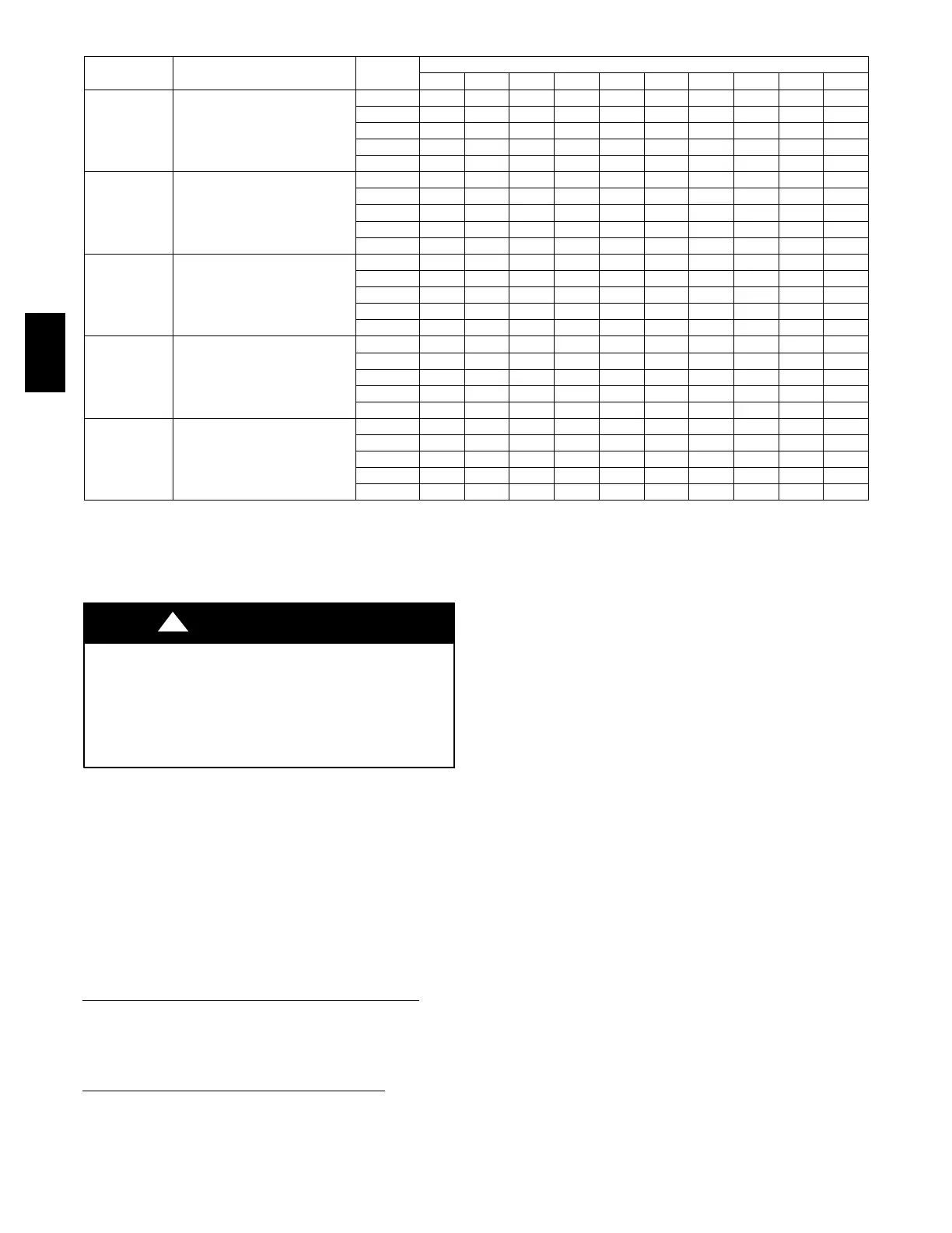
Table 18 – Speed Selection
UNIT SIZE RETURN --- AIR SUPPLY SPEED
EXTERNAL STATIC PRESSURE (in. wc)
0.1 0.2 0.3 0.4 0.5 0.6 0.7 0.8 0.9 1
060---12 SIDE/BOTTOM
5(Gry) 1430 1390 1345 1300 1250 1205 1150 1080 995 845
3(Blu) 1240 1200 1145 1100 1040 975 915 860 790 730
4(Yel) 1090 1030 980 935 850 800 730 665 590 525
1(Red) 900 835 780 705 635 565 490 410 335 200
2(Org) 805 620 440 380 300 --- --- --- --- ---
080---12 SIDE/BOTTOM
5(Gry) 1400 1360 1325 1285 1240 1205 1160 1125 1075 1000
3(Blu) 1340 1300 1265 1215 1180 1135 1100 1055 1015 965
4(Yel) 1195 1160 1115 1065 1025 985 935 895 850 800
1(Red) 1025 980 935 880 835 795 745 685 635 585
2(Org) 855 800 745 680 635 560 515 460 420 360
080---16 SIDE/BOTTOM
5(Gry) 1720 1695 1690 1655 1620 1580 1540 1495 1465 1415
3(Blu) 1565 1535 1530 1490 1450 1420 1375 1335 1295 1255
4(Yel) 1330 1310 1270 1220 1180 1135 1095 1055 1010 970
2(Org) 1210 1180 1135 1085 1035 995 950 910 865 810
1(Red) 1110 1065 1005 960 910 865 820 770 720 670
100---20 SIDE/BOTTOM
5(Gry) 2070 2020 1985 1925 1890 1850 1795 1755 1690 1610
3(Blu) 1815 1775 1730 1690 1635 1595 1555 1500 1460 1410
4(Yel) 1580 1535 1480 1440 1380 1380 1340 1285 1235 1185
2(Org) 1380 1325 1275 1220 1220 1165 1105 1060 1000 960
1(Red) 1170 1105 1055 985 935 870 805 765 705 660
120---20 SIDE/BOTTOM
5(Gry) 2250 2205 2155 2110 2065 2020 1970 1925 1870 1790
3(Blu) 2130 2085 2030 1980 1925 1880 1830 1775 1730 1675
4(Yel) 1890 1835 1790 1740 1690 1640 1590 1535 1480 1435
1(Red) 1640 1585 1525 1475 1425 1365 1315 1260 1200 1140
2(Org) 1420 1370 1305 1255 1190 1135 1065 1010 940 880
NOTES:
* Airflow shown is with factory supplied 3/4---in. (19 mm) washable filter.*A filter is required for each return air opening.
*An airflow reduction of up to 7% may occur when using the factory---specified 4---5/16---in. (110 mm) wide, high efficiency media filter.
*For best furnace efficiency when using the 4 5/16---in. (110 mm) wide media filter, adjustblowerspeedtaptonearthemid---pointoftheriserange.
*For horizontal and downflow applications, use one side or bottom or bottom only as an airflow reference.
(Read following caution before changing taps).
UNIT DAMAGE HAZARD
To avoid operating outside the rise range and avoid
component damage:
1. NEVER connect Speed Tap 1 (Red) wire to “HI HT.”
2. NEVER connect Speed Tap 2 (Orange) wire to “HI HT”
on all models.
CAUTION
!
To change blower motor speed selections for heating mode,
remove blower motor lead from control HI-HT terminal. (See
Fig. 37.) Select desired blower motor speed lead from one of the
other motor leads and relocate it to HI-HT terminal. (See Table
18 for lead color identification.) Reconnect original lead on
SPARE terminal. Follow this same procedure for proper selection
of LO-HT and COOL speed selection.
Set Blower Off Delay
a. Remove Blower Access Door if installed.
b.TurnDipswitch2and3ONorOFFfordesired
blower off delay. See Tables 13 and 14 or Fig. 36 and
37.
ADJUST BLOWER OFF DELAY (HEAT MODE)
If desired, the main blower off time delay period may be
lengthened or shortened when operating in the heating mode to
provide greater comfort. See Table 13 for position of switches
and Fig. 36 or 37. for location of switches on control center.
SETTHERMOSTATHEATANTICIPATOR
When using a nonelectronic thermostat, the thermostat
heat-anticipator must be set to match the amp draw of
the electrical components in R-W/W1 circuit. Accurate amp
draw readings can be obtained at thermostat subbase terminals
RandW.
Fig. 61 illustrates an easy method of obtaining actual amp draw.
The amp reading should be taken after blower motor has started
and furnace is operating in low heat. To operate furnace in
low-heat, first move SW-1 to ON position, then connect ammeter
wires as shown in Fig. 61. The thermostat anticipator should
NOT be in the circuit while measuring current. If thermostat has
no subbase, the thermostat must be disconnected from R and
W/W1 wires during current measurement Return SW-1 to final
desired location after completing the reading.
See thermostat manufacturer’s instructions for adjusting heat
anticipator and for varying heating cycle length.
When using an electronic thermostat, set cycle rate for 3 cycles
per hour.
Step 6 -- Check Safety Controls
This section covers the safety controls that must be checked
before the installation is complete. The flame sensor, gas valve,
and pressure switch were all checked in the Start-up procedure
section as part of normal operation.
1. Check Primary Limit Control
This control shuts off gas control system and energizes
air-circulating blower motor if furnace overheats.
Recommended method of checking this limit control is to
gradually block off return air after furnace has been
operating for a period of at least 5 minutes. As soon as
limit control has shut off burners, return-air opening
should be unblocked to permit normal air circulation. By
using this method to check limit control, it can be
established that limit is functioning properly and operates
if there is a restricted return-air supply or motor failure. If
limit control does not function during this test, cause must
be determined and corrected.
58MEC
 Loading...


