47
OPEN STAND
PIPE FOR
A/C OR
HUMIDIFIER
DRAIN
TEE
TO OPEN
DRAIN
A94054
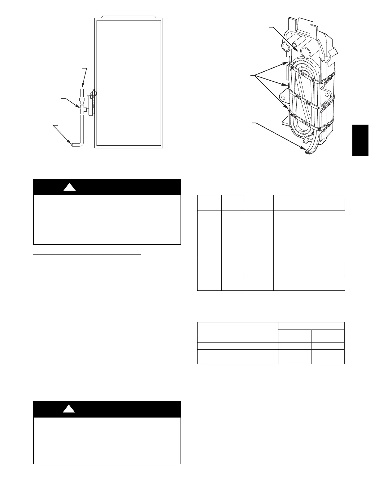
Fig. 46 -- Example of Field Drain Attachment
PERSONAL INJURY AND PROPERTY DAMAGE
HAZARD
Failure to follow this warning could result in property damage,
personal injury, or death.
Excessive condensate draining may cause saturated soil
conditions which could result in damage to plants.
!
WARNING
CONDENSATE DRAIN PROTECTION
Freezing condensate left in condensate trap and drain line may
cause cracks, and possible water damage may occur. If freeze
protection is required, use condensate freeze protection accessory
or equivalent 3 to 6 watt per ft at 120-v and 40°F(4°C)
self-regulating, shielded, and waterproof heat tape. See
Installation Instructions supplied with accessory or heat tape
manufacturer’s recommendations.
1. Fold heat tape in half and wrap on itself 3 times.
2. Locate heat tape between sides of condensate trap back.
(See Fig. 47.)
3. Use wire ties to secure heat tape in place. Wire ties can be
positioned in notches of condensate trap sides. (See Fig.
47.)
4. Wrap field drain pipe with remaining heat tape,
approximately 1 wrap per ft.
5. When using field-supplied heat tape, follow heat tape
manufacturer’s instructions for all other installation
guidelines.
START-UP ADJUSTMENT AND
SAFETY CHECK
FURNACE MAY NOT OPERATE
Failure to follow this caution may result in furnace operation
stopping and water pipes freezing during cold weather.
Furnace control must be grounded for proper operation, or
control will lockout. Control is grounded through green/yellow
wire connected to gas valve C-terminal and burner box screw.
CAUTION
!
CONDENSATE TRAP
WIRE TIE(S)
HEAT TAPE
(3 WRAPS MINIMUM)
A93036
Fig. 47 -- Condensate Trap Heat Tape
Table 13 – Furnace Setup Switch Description
SETUP
SWITCH
NO.
SWITCH
NAME
NORMAL
POSITION
DESCRIPTION OF USE
S W --- 1
Adaptiv
eHeat
Mode
OFF
When off, allows 2---stage
operation with a
single---stage thermostat.
Tu r n on w h e n u s i n g 2 --- s t a g e
thermostat to allow Low
Heat operation when R to
W/W1 closes and High Heat
operationwhenRtoW/W1
and W2 close.
S W --- 2
Blower
OFF
delay
ON or
OFF
Control blower OFF delay
time. Used in conjunction
with SW---3. See Table 14.
S W --- 3
Blower
OFF
delay
ON or
OFF
Control blower OFF delay
time. Used in conjunction
with SW---2. See Table 14.
Table 14 – Blower Off Delay Setup Switch (SW)
2-Stage Units
DESIRED HEATING MODE
BLOWER-OFF DELAY (SEC)
SETUP SWITCH
S W --- 2 S W --- 3
90 OFF OFF
120 OFF ON
150 ON OFF
180 ON ON
Step 1 -- General
The furnace must have a 115-v power supply properly connected
and grounded.
NOTE: Proper polarity and proper grounding must be
maintained for 115-v wiring. If polarity is incorrect or furnace is
not grounded, control status indicator light will flash rapidly and
the furnace will not operate.
Natural gas service pressure must not exceed 0.5 psig (14-IN.
WC),andbenolessthan0.16psig(4.5-IN.WC).
Thermostat wire connections at R and W/W1 are the minimum
required for gas heating operation. W2 must be connected for
2-stage heating thermostats. C
OM, Y/Y2, and G are required for
cooling, heat pumps, and some clock thermostats. These must be
made at the 24-v terminal block on the control. (See Fig. 37.)
58MEC
 Loading...


