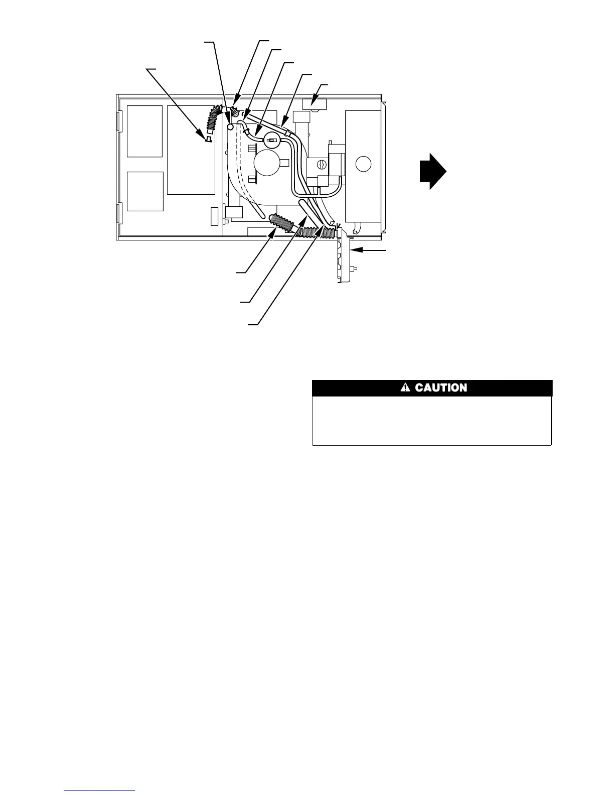
1. Disconnect collector box pressure tube (pink label) attached to
pressure switch.
2. Use smaller diameter tube (factory-supplied in loose parts
bag) to extend collector box pressure tube (green label) which
was previously connected to condensate trap relief port
connection.
3. Route extended collector box pressure tube behind inducer
motor bracket then between inducer motor and pressure
switch.
4. Connect collector box pressure tube (green label) to pressure
switch connection labeled COLLECTOR BOX.
5. Use remaining smaller diameter tube (factory-supplied in
loose parts bag) to extend collector box pressure tube (pink
label) which was previously connected to pressure switch.
6. Route this extended tube (pink label) to condensate trap relief
port connection.
7. Determine appropriate length, cut, and connect tube.
8. Clamp tube to relief port connection.
CONDENSATE TRAP FREEZE PROTECTION
Refer to Condensate Drain Protection section for recommenda-
tions and procedures.
CONSTRUCT A WORKING PLATFORM
Construct working platform where all required furnace clearances
are met. (See Fig. 3 and 11.)
The condensate trap MUST be installed below furnace. See
Fig. 5 for dimensions. The drain connection to condensate
trap must also be properly sloped to an open drain. Failure to
follow this caution will result in intermittent unit operation.
NOTE: Vent pipe length is restricted to a minimum of 5 ft. (See
Table 6.)
NOTE: A 12-in. minimum horizontal pipe section is recom-
mended with short (5 to 8 ft) vent systems. This recommendation
is to reduce excessive condensate droplets from exiting the vent
pipe. (See Fig. 11 or 38.)
LOCATION
Step 1—General
This furnace must
• be installed so the electrical components are protected from
water.
• not be installed directly on any combustible material other than
wood flooring (refer to SAFETY CONSIDERATIONS).
• be located so combustion-air and vent pipe maximum lengths
are not exceeded. Refer to Table 6.
• be located where available electric power and gas supplies meet
specifications on the furnace rating plate.
• be attached to an air distribution system and be located as close
to the center of the distribution system as possible. Refer to Air
Ducts section.
• be provided with ample space for servicing and cleaning.
Always comply with minimum fire protection clearances
shown on the furnace clearance-to-combustibles label.
Fig. 12—Horizontal Right Tube Configuration
A00214
PLUG
COLLECTOR BOX DRAIN TUBE
(BLUE AND WHITE STRIPED)
INDUCER HOUSING
DRAIN TUBE (VIOLET)
COLLECTOR BOX
EXTENSION TUBE
COLLECTOR BOX TUBE (GREEN)
CAP
COLLECTOR BOX DRAIN TUBE (BLUE)
COLLECTOR BOX TUBE (PINK)
CONDENSATE
TRAP
COLLECTOR BOX EXTENSION TUBE
AUXILARY “J” BOX RELOCATED HERE
12
→
 Loading...