In the United States and Canada, follow all codes and standards for
the following:
Step 1—Safety
• US: National Fuel Gas Code (NFGC) NFPA 54-2002/ANSI
Z223.1-2002 and the Installation Standards, Warm Air Heating
and Air Conditioning Systems ANSI/NFPA 90B
• CANADA: National Standard of Canada, Natural Gas and
Propane Installation Code (NSCNGPIC) CSA B149.1-00.
Step 2—General Installation
• US: NFGC and the NFPA 90B. For copies, contact the National
Fire Protection Association Inc., Batterymarch Park, Quincy,
MA 02269; or for only the NFGC contact the American Gas
Association, 400 N. Capitol, N.W., Washington DC 20001
• CANADA: NSCNGPIC. For a copy, contact Standard Sales,
CSA International, 178 Rexdale Boulevard, Etobicoke
(Toronto), Ontario, M9W 1R3, Canada.
Step 3—Combustion and Ventilation Air
• US: Section 5.3 of the NFGC, Air for Combustion and
Ventilation
• CANADA: Part 7 of the NSCNGPIC, Venting Systems and Air
Supply for Appliances
Step 4—Duct Systems
• US and CANADA: Air Conditioning Contractors Association
(ACCA) Manual D, Sheet Metal and Air Conditioning Con-
tractors National Association (SMACNA), or American Soci-
ety of Heating, Refrigeration, and Air Conditioning Engineers
(ASHRAE) 2001 Fundamentals Handbook Chapter 34.
Step 5—Acoustical Lining and Fibrous Glass Duct
• US and CANADA: current edition of SMACNA, NFPA 90B as
tested by UL Standard 181 for Class I Rigid Air Ducts
Step 6—Gas Piping and Gas Pipe Pressure Testing
• US: NFGC; chapters 2, 3, 4, and 9 and national plumbing codes
• CANADA: NSCNGPIC Parts 3, 4, 5, A, B, E, and H.
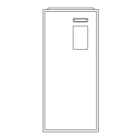
Fig. 3—Clearances to Combustibles
A02248
This forced air furnace is equipped for use with natural gas at altitudes 0 - 10,000 ft (0 - 3,050m), except 140 size furnaces are only approved for altitudes 0 - 7,000 ft.
(0 - 2,135m).
An accessory kit, supplied by the manufacturer, shall be used to convert to propane gas use or may be required for some natural gas applications.
This furnace is for indoor installation in a building constructed on site. This furnace may be installed in a manufactured (mobile) home when stated on rating plate and
using factory authorized kit.
This furnace may be installed on combustible flooring in alcove or closet at
Minimum Inches Clearance To Combustible Construction
as described below.
This furnace requires a special venting system. Refer to the installation instructions for parts list and method of installation. This furnace is for use with schedule-40 PVC,
PVC-DWV, CPVC, or ABS-DWV pipe, and must not be vented in common with other gas-fired appliances. Construction through which vent/air intake pipes may be
installed is maximum 24 inches (600 mm), minimum 3/4 inches (19 mm) thickness (including roofing materials).
MINIMUM INCHES CLEARANCE TO COMBUSTIBLE CONSTRUCTION
*
Minimum front clearance for service 30 inches (762mm).
140 size furnaces require 1 inch back clearance to combustible materials.
For installation on combustible floors only when installed on special base No. KGASB0201ALL,
Coil Assembly, Part No. CD5 or CK5, or Coil Casing, Part No. KCAKC.
Line contact is permissible only between lines formed by intersections of top and two sides of
furnace jacket, and building joists, studs, or framing.
Clearance shown is for air inlet and air outlet ends.
120 and 140 size furnaces require 1 inch bottom clearance to combustible materials.
Ø
Clearance in inches.
Vent clearance to
combustibles 0".
This furnace is approved for UPFLOW, DOWNFLOW and
HORIZONTAL installations.
*
BOTTOM
0"
Ø
3"
0"
§
0"
TOP/PLENUM
1"
0"
§
30
MIN
ALL POSITIONS:
DOWNFLOW POSITIONS:
HORIZONTAL POSITIONS:
S
I
D
E
F
R
O
N
T
B
C
K
A
S
E
R
V
I
E
C
F
R
O
N
T
S
I
D
E
U
F
R
N
A
C
E
Clearance arrows
do not change with
furnace orientation.
†
†
†
†
UPFLOW OR
DOWNFLOW
1/2" MAX
LEVEL (0")
TO
†
†
328066-201 REV. A
LIT -TOP
INSTALLATION
§
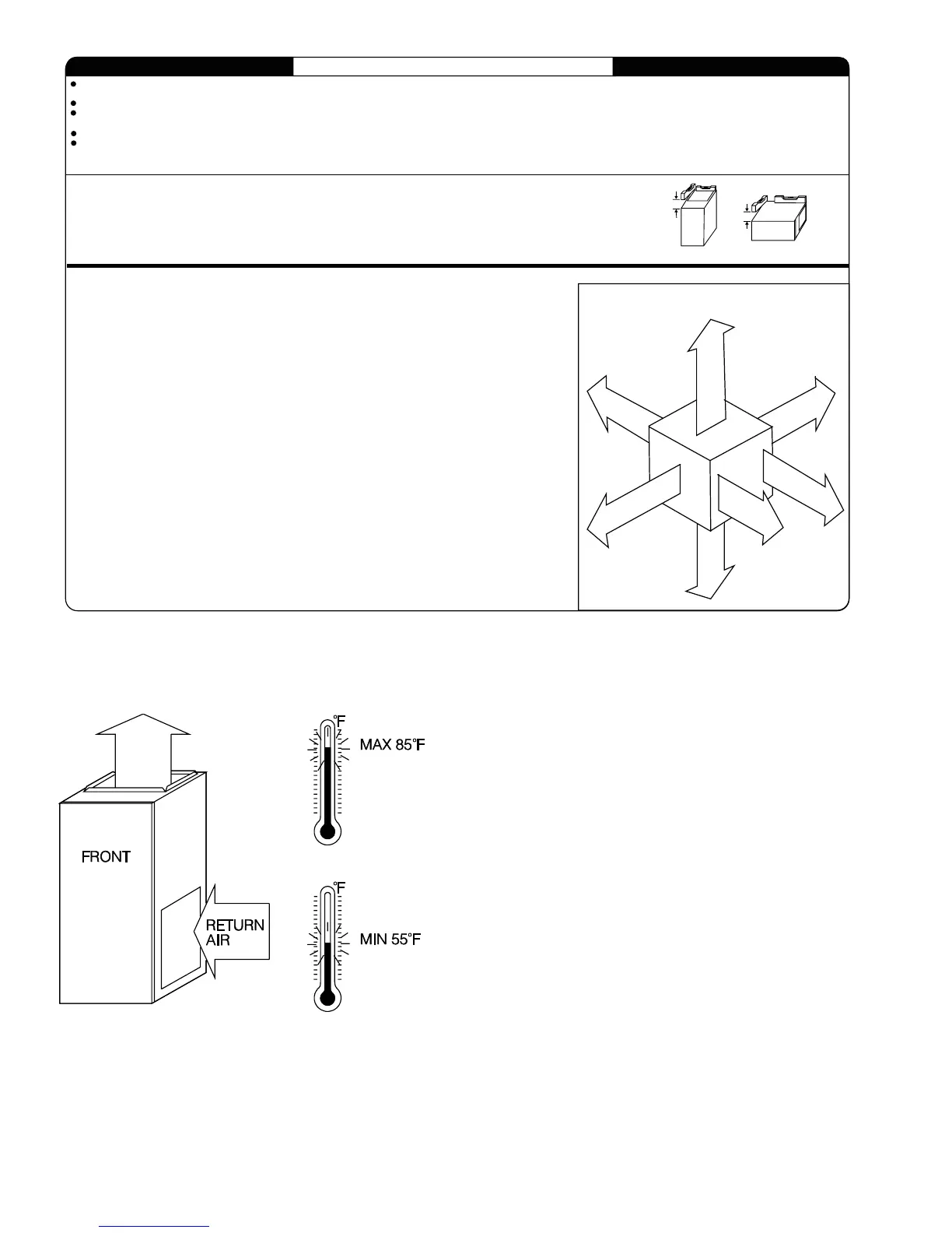
For upflow and downflow applications, furnace must be installed level, or pitched within 1/2" of level. For a
horizontal application, the furnace must be pitched minimum 1/4" to maximum of 1/2" forward for proper
drainage. See Installation Manual for IMPORTANT unit support details on horizontal applications.
HORIZONTAL
FRONT
FRONT
MIN 1/4" TO 1/2" MAX
Fig. 4—Return-Air Temperature
A94163
4
 Loading...