Unit must not be installed, operated, and then turned off and
left in an unconditioned structure during cold weather when
temperature drops to 32 degrees F and below unless drain trap
and drain line have adequate freeze protection. See Service
and Maintenance Instructions for winterizing procedures.
(See Fig. 15.) Failure to follow this caution will result in
minor unit operation.
Furnace condensate is mildly acidic, typically in the pH range of
3.2 to 4.5. Due to corrosive nature of unneutralized condensate, a
condensate pH neutralizing filter may be desired. Check with local
authorities to determine if a pH neutralizer is required.
Step 2—Application
The furnace, A/C, and humidifier drains may be combined and
drained together. The A/C drain must have an external, field-
supplied trap prior to the furnace drain connection. All drain
connections (furnace, A/C, or humidifier) must be terminated into
an open or vented drain as close to the respective equipment as
possible to prevent siphoning of the equipment’s drain.
See Fig. 42 for example of possible field drain attachment using
1/2-in. CPVC or PVC tee for vent and A/C or humidifier drain
connection.
Outdoor draining of the furnace is permissible if allowed by local
codes. Caution should be taken when freezing ambient may freeze
drain pipe and prohibit draining.
Caution should be taken to prevent draining where slippery
conditions may cause personal injuries. Excessive condensate
draining may cause saturated soil conditions which may result
in damage to plants.
Step 3—Condensate Drain Protection
Freezing condensate left in condensate trap and drain line may
cause cracks, and possible water damage may occur. If freeze
protection is required, use condensate freeze protection accessory
or equivalent 3 to 6 watt per ft at 120v and 40°F self-regulating,
shielded, and waterproof heat tape. See Installation Instructions
supplied with accessory or heat tape manufacturer’s recommenda-
tions.
1. Fold heat tape in half and wrap on itself 3 times.
2. Locate heat tape between sides of condensate trap back. (See
Fig. 43.)
3. Use wire ties to secure heat tape in place. Wire ties can be
positioned in notches of condensate trap sides. (See Fig. 43.)
4. Wrap field drain pipe with remaining heat tape, approximately
1 wrap per ft.
5. When using field-supplied heat tape, follow heat tape manu-
facturer’s instructions for all other installation guidelines.
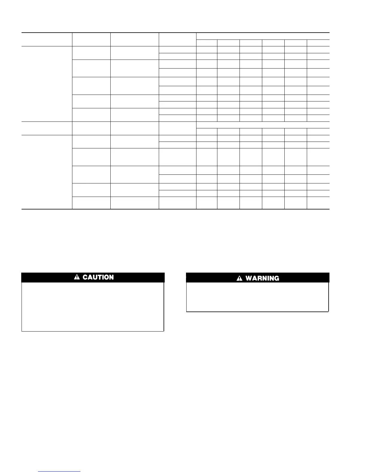
Table 6—Maximum Allowable Pipe Length (ft) (Continued)
ALTITUDE (FT) UNIT SIZE
TERMINATION
TYPE
PIPE DIA
(IN.)*
NUMBER OF 90° ELBOWS
123456
8001 to 9000‡
040-08
040-12
2 Pipe or 2-in
Concentric
1-1/2 46 41 36 31 29 24
2 626058565553
060-08
060-12
060-16
2 Pipe or 2-in
Concentric
1-1/2 11 6 NA NA NA NA
2 494442373534
080-12
080-16
080-20
2 Pipe or 2-in
Concentric
2 3328171210NA
2-1/2 62 60 58 56 55 53
100-16
100-20
2 Pipe or 3-in
Concentric
2-1/2 23 15 7 5 NA NA
3 595449443934
120-20
2 Pipe or 3-in.
Concentric
3† no disk 10 NA NA NA NA NA
4† no disk 35 30 25 20 15 10
ALTITUDE (FT) UNIT SIZE
TERMINATION
TYPE
PIPE DIA
(IN.)*
NUMBER OF 90° ELBOWS
123456
9001 to 10,000‡
040-08
040-12
2 Pipe or 2-in
Concentric
1-1/2 42 37 32 27 25 20
2 575553514947
060-08
060-12
060-16
2 Pipe or 2-in
Concentric
2 454038333129
080-12
080-16
080-20
2 Pipe or 2-in
Concentric
230251497NA
2-1/2 57 55 53 51 49 47
100-16
100-20
2 Pipe or 3-in
Concentric
2-1/2 21 13 5 NA NA NA
3 544944393429
120-20
2 Pipe or 3-in.
Concentric
4† no disk 10 5 NA NA NA NA
Disk usage-Unless otherwise specified, use perforated disk assembly (factory-supplied in loose parts bag). If one disk is stated, separate 2 halves of perforated disk
assembly and use shouldered disk half. When using shouldered disk half, install screen side toward inlet box.
†Wide radius elbow.
‡Vent sizing for Canadian installations over 4500 ft (1370 m) above sea level are subject to acceptance by the local authorities having jurisdiction.
NA-Not Allowed; pressure switch will not make.
NOTES:
1. Do not use pipe size greater than those specified in table or incomplete combustion, flame disturbance, or flame sense lockout may occur.
2. Size both the combustion-air and vent pipe independently, then use the larger diameter for both pipes.
3. Assume two 45° elbows equal one 90° elbow. Long radius elbows are desirable and may be required in some cases.
4. Elbows and pipe sections within the furnace casing and at the vent termination should not be included in vent length or elbow count.
5. The minimum pipe length is 5 ft for all applications.
6. Use 3-in. diameter vent termination kit for installations requiring 4-in diameter pipe.
32
→