12
CONDENSATE TRAP
Condensate Trap -- Upflow Orientation
When the furnace is installed in the upflow position, it is not
necessary to relocate the condensate trap or associated tubing.
Refer to Fig. 9 for upflow condensate trap information. Refer to
Condensate Drain section for information how to install the
condensate drain.
Condensate Trap -- Downflow Orientation.
When the furnace is installed in the downflow position, the
condensate trap will be initially located at the upper left corner of
the collector box, as received from the factory. See the top image
in Fig. 10. When the furnace is installed in the downflow
orientation, the condensate trap must be relocated for proper
condensate drainage. See the bottom image in Fig. 10.
To Relocate the Condensate Trap:
S Orient the furnac e in the downf low pos i ti on.
S Fig. 10 shows t he condensate tr ap and tubi ng be for e and af t er
rel oca ti on. Refer to Fig. 10 to begin t he tr ap conver si on.
S Refer t o Conde nsat e D r ain sect ion for inf or m at ion how to instal l the
condensate dra in.
Condensate Trap -- Horizontal Orientation.
Whe n the furnace is inst al le d in the horizont al ri ght posi t ion, the
condensate trap wil l be initially located at the bottom of the collector
box, as received from the factory . See the top image in Fig. 11.
When the furnace is installed in the horizontal left position, the
condensate trap will be initially located at the top of the collector box,
as received from the factory. See the top image in Fig. 12. In both
cases the t rap mus t be re positi oned on the colle ctor box for proper
condensate dra ina ge. Se e the bottom ima ges in Fig. 1 1 a nd 12.
A field--supplied, accessory Horizontal Installation Kit (trap
grom met) i s requi re d for all dire ct--ve nt hori zontal inst al lat i ons (onl y).
The kit conta ins a rubber c as ing grommet desi gned to sea l be twee n
the furna ce ca sing and the condensate tr ap. See Fig. 8.
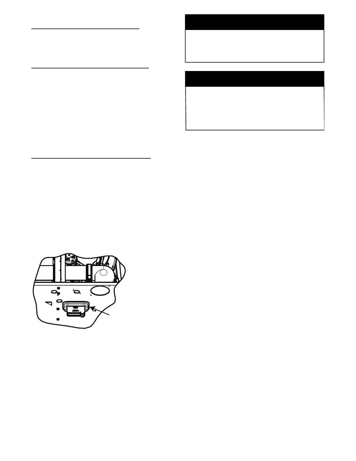
Remove knockout.
Install grommet before
relocating condensate
trap.
NOTE: Trap grommet is required only for direct-vent
applications.
A11582
Fig. 8 -- Horizontal Drain Trap Grommet
The field--supplied, accessory horizontal drain trap grommet is
ONLY REQUIRED FOR DIRECT VENT APPLICATIONS.
It it NOT required for applications using single-- pipe or
ventilated combustion air venting.
NOTICE
The condensate trap extends below the side of the casing in
the horizontal position. A minimum of 2--in. (51 mm) of
clearance is required between the casing side and the furnace
platform for the trap to extend out of the casing in the
horizontal position. Allow at least 1/4-- in. per foot (20 mm
per meter) of slope down.
NOTICE
To Relocate the Condensate Trap:
S Remove t he knockout in the casi ng f or the conde nsat e tr ap.
S Insta ll t he grommet i n the ca si ng whe n required for dir ec t--vent
horiz ontal a ppli cations .
S Orient the furnace in the desired position.
S Allow f or 2 i n. (51 mm) of cl ea rance underneat h the furnac e for the
condensate tr ap and drain line.
S Fig. 11 s hows the c ondens at e trap and tubing befor e and af t er
rel ocati on i n the horizont al ri ght posi ti on.
S Fig. 12 shows t he condensate tr ap and tubi ng be for e and af t er
rel ocati on i n the horizont al l eft posit ion.
S Refer t o t he appr opri ate figur e to begin the tra p c onver si on.
S Refer t o Conde nsat e D r ain sect ion for inf or m at ion how to instal l the
condensate dra in.