70
Table 2 1 (Continued) -- Orifice Size a nd Manifold Pressure (in. w.c.) for Gas Input Rate
26,000 BTUH ONLY
650
43 1.7 43 1.8 42 1.5 42 1.6
7001 675 44 1.8
43 1.7 43 1.7 43 1.8
(2134) 700 44 1.7 44 1.8 44 1.8
43 1.7
725 44 1.6 44 1.7 44 1.7 44 1.8
750 44 1.5 44 1.5 44 1.6 44 1.6
8000 775 44 1.4 44 1.4 44 1.5 44 1.5
(2438) 800 44 1.3 44 1.4 44 1.4 44 1.4
825 44 1.2 44 1.3 44 1.3 44 1.4
625
43 1.7 43 1.8 43 1.8 42 1.6
8001 650 44 1.8
43 1.7 43 1.7 43 1.8
(2439) 675 44 1.7 44 1.8 44 1.8
43 1.6
700 44 1.6 44 1.6 44 1.7 44 1.7
725 44 1.5 44 1.5 44 1.6 44 1.6
9000 750 44 1.4 44 1.4 44 1.5 44 1.5
(2743) 775 44 1.3 44 1.3 44 1.4 44 1.4
9001 600
43 1.7 43 1.8 43 1.8 42 1.6
(2744) 625 44 1.8
43 1.6 43 1.7 43 1.7
650 44 1.7 44 1.7 44 1.8 44 1.8
675 44 1.6 44 1.6 44 1.7 44 1.7
10000 700 44 1.4 44 1.5 44 1.5 44 1.6
(3048) 725 44 1.3 44 1.4 44 1.4 44 1.5
* Orifice numbers shown in BOLD are factory-installed.
U.S.A. Only
to
U.S.A. Only
to
U.S.A. Only
to
ORIFICE SIZE* AND MANIFOLD PRESSURE (IN WC) FOR GAS INPUT RATE
TABULATED DATA BASED ON 13,000 BTUH PER BURNER, DERATED 2%/1000 FT (305M) ABOVE SEA LEVE
A150572
Check Inlet Gas Pr essur e
The inlet gas pressure must be checked with the furnace operating
in maximum heat. This is necessary to make sure the inlet gas
pressure does not fall below the minimum pressure of 4.5 in. w.c.
1. Make sure the gas supply is turned off to the furnace and at
the electric switch on the gas valve.
2. Loosen set screw on inlet tower pressure tap no more than
one full turn with a 3/32--in. hex wrench or remove the
1/8--in. NPT plug from the inlet pressure tap on the gas
valve.
3. Connect a manometer to the inlet pressure tap on gas valve.
4. Turn on furnace power supply.
5. Turn gas supply manual shutoff valve to ON position.
6. Turn furnace gas valve switch to ON position.
7. Jumper R and W thermostat connections at the furnace
control board.
8. When main burners ignite, confirm inlet gas pressure is
between 4.5 in. w.c. (1125 Pa) and 13.6 in. w.c. (3388 Pa).
9. Remove jumper across thermostat connections to terminate
call for heat. Wait until the blower off delay is completed.
10. Turn furnace gas valve electric switch to OFF position.
11. Turn gas supply manual shutoff valve to OFF position.
12. Turn off furnace power supply.
13. Remove manometer from the inlet pressure tap of the gas
valve.
FIRE HAZARD
Failure to follow this warning could result in personal injury,
death, and/or property damage.
Inlet pressure tap set screw must be tightened and 1/8--in. NPT
pipe plug must be installed to prevent gas leaks.
!
WARNING
14. Tighten set screw on inlet tower pressure tap with 3/32--in.
hex wrench, or if 1/8--in. NPT plug was removed, apply
pipe dope sparingly to end of plug and re--install in the gas
valve.
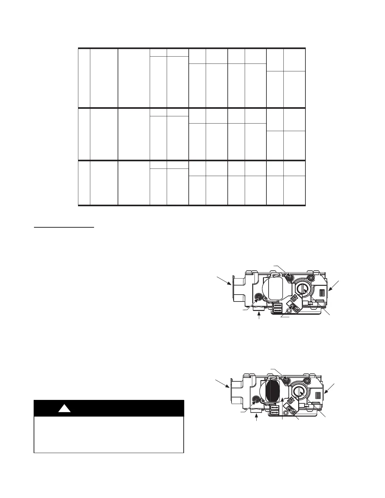
ON/OFF SWITCH
1/8” NPT INLET
PRESSURE TAP
REGULATOR SEAL CAP
(REGULATOR ADJ.
UNDER CAP)
1/2” NPT
OUTLET
MANIFOLD PRESSURE TAP
SET SCREW: 3/32” HEX HEAD
ACCEPTS 5/16” HOSE CONNECTION
OUTP
INP
VENT
1/2” NPT
INLET
INLET PRESSURE
TAP SET SCREW:
3/32” HEX HEAD
ACCEPTS 5/16”
HOSE CONNECTION
Representative drawing only, some models may vary in appearance.
A170140
Standard Capacity Gas Valve with Tower Pressure Ports
1/8” NPT INLET
PRESSURE TAP
REGULATOR SEAL CAP
(REGULATOR ADJ.
UNDER CAP)
1/2” NPT
OUTLET
MANIFOLD PRESSURE TAP
SET SCREW: 3/32” HEX HEAD
ACCEPTS 5/16” HOSE CONNECTION
OUTP
INP
VENT
1/2” NPT
INLET
INLET PRESSURE
TAP SET SCREW:
3/32” HEX HEAD
ACCEPTS 5/16”
HOSE CONNECTION
Representative drawing only, some models may vary in appearance.
Green Label
Black Text
ON/OFF
SWITCH
1.5”
W.C
.
White Label
Black Text
A170118
26,000 BTUH Low Capacity Gas Valve with Tower Pressure
Ports
Fig. 60 -- Gas Valves
 Loading...


