NOTE:
Units equipped with speed regulators (30RB/30RQ option 6B,
12, 15LS, 28, 116V, 116W, 116X, 116Y).
If the air temperature is below -10 °C and the unit has been
deenergised for more than 4 hours, it is necessary to wait
two hours after the unit has been switched on again to allow
the regulator to warm up.
7.2 - Minimum heat transfer uid ow rate
(units without factory-tted hydraulic module)
The minimum heat transfer uid ow rate for dierent unit sizes
is given in the tables in paragraph "Water type heat exchanger
ow rate".
It is determined in order to allow sucient exchange and prevent
the risk of excessive fouling.
If the system ow rate is less than the unit's minimum ow rate,
the exchanger ow can be recirculated, as shown in the diagram.
Key
1 Water type heat exchanger
2 Recirculation
7.3 - Maximum heat transfer uid ow rate
(units without factory-tted hydraulic module)
The maximum heat transfer uid ow rate for dierent unit sizes
is given in the tables in paragraph "Water type heat exchanger
ow rate".
This is limited by the permitted exchanger pressure drop. In
addition, there must be a minimum Delta T of 3 K, which
corresponds to a ow rate of 0.09 l/s per kW.
If the system ow rate exceeds the unit's maximum value, it can
be bypassed as shown in the diagram.
Key
1 Water type heat exchanger
2 Bypass
7.4 - Variable ow water type heat exchanger
(units without factory-tted hydraulic module)
A variable water heat exchanger ow can be used in standard
units. The ow rate must be higher than the minimum ow given
in the table of permissible ow rates and must not vary by more
than 10% per minute.
If the ow rate changes more rapidly, the system's water volume
should be increased and reach a value of at least 6.5 litres of water
per kW.
7.5 - Minimum system water volume
Whichever system, water volume for the water loop (to be provided
between the unit and any customer valves outside the machine)
is given by the formula
Volume = Cap (kW) x N litres
Application N
Air conditioning – cooling 2,5
Air conditioning – heating 3,0 - 8,0
(1)
Industrial process type cooling 6,5
(1) Depending on the unit capacity - minimum water loop volume 1300 l
Where "Cap" represents the cooling or heating capacity (kW)
under the installation's nominal operating conditions. This volume
is necessary for stable operation. It may be necessary to add a
buer water tank to the circuit in order to achieve the minimum
volume. The tank must itself be internally baed in order to ensure
proper mixing of the liquid (water or brine). Refer to the examples
below.
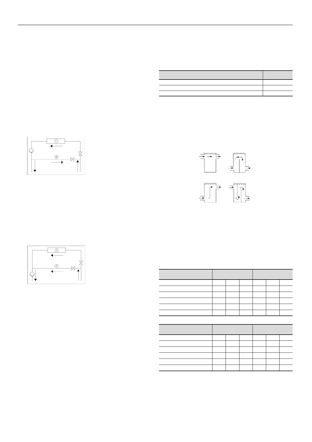
Connection to a buer tank
CorrectIncorrect
Incorrect Correct
7.6 - Maximum system water volume
Units with a hydraulic module may include an expansion vessel
which limits the volume in the water loop.
The table below gives the maximum loop volume compatible with
the expansion vessel (for pure water or ethylene glycol depending
on the system's various concentrations and static pressures).
If this volume is less than the volume of the installed loop, then it
is necessary to add an extra expansion vessel within the system.
Product
040-080 without
buer tank
090-160 without
buer tank
Static pressure bar 1 2 3 1 2 3
Pure water l 597 398 199 1741 1161 580
10% EG l 471 314 157 1373 915 458
20% EG l 389 259 130 1135 757 378
30% EG l 348 232 116 1014 676 338
40% EG l 289 193 96 843 562 281
Product
040-080 without
buer tank
090-160 without
buer tank
Static pressure bar 1 2 3 1 2 3
Pure water l 896 597 299 1741 1161 580
10% EG l 706 471 235 1373 915 458
20% EG l 584 389 195 1135 757 378
30% EG l 522 348 174 1014 676 338
40% EG l 434 289 145 843 562 281
EG: Ethylene Glycol
7 - APPLICATION DATA
22
 Loading...