8 - WATER CONNECTIONS
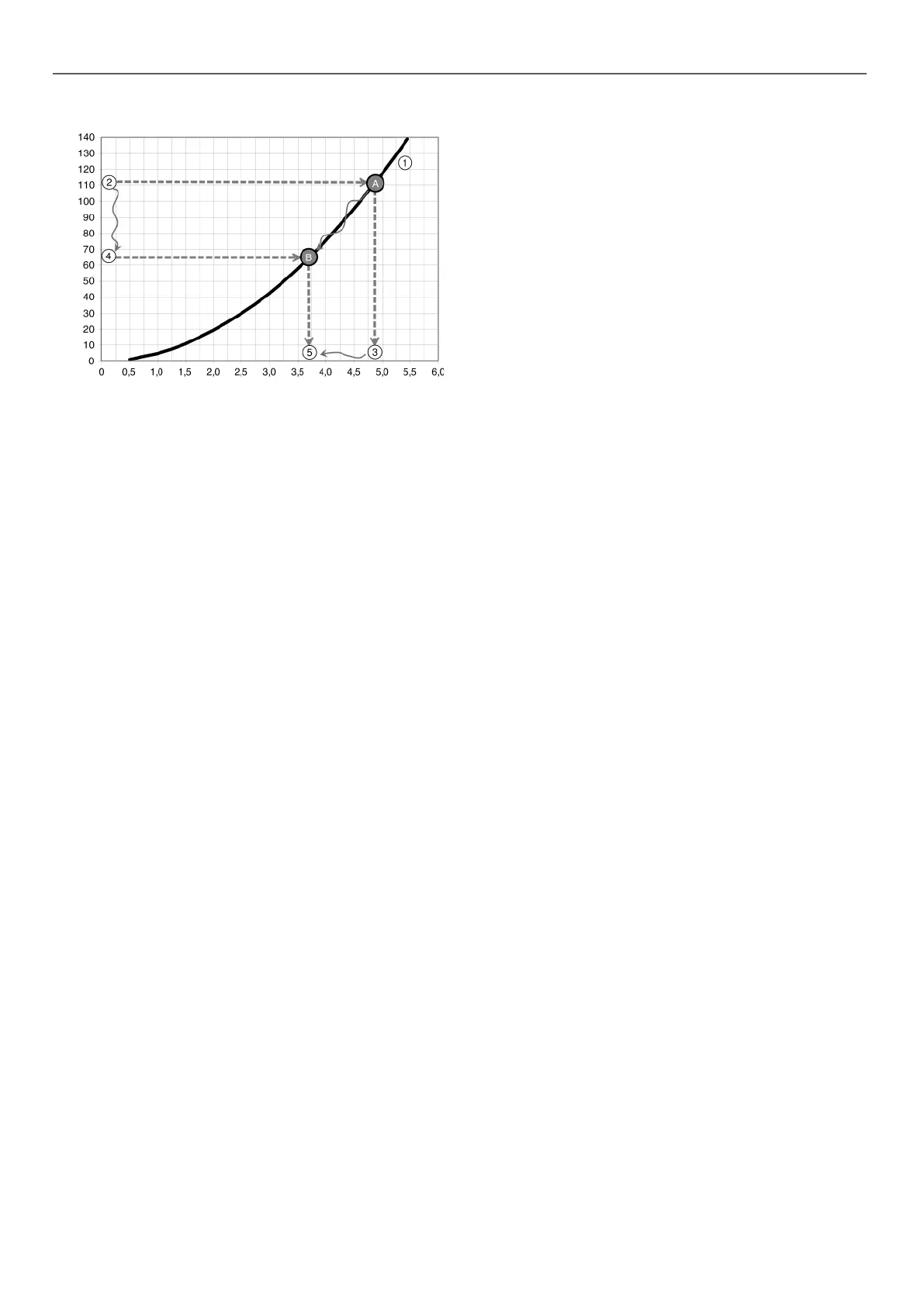
Example : Unit with specic nominal ow 3.7 l/s
Water ow rate, l/s
Pressure drop, kPa
Key
1 "Unit pressure drop (including internal water circuits)/ow rate" curve
2 With the valve open the pressure drop read (111 kPa) gives point A on the curve.
A Operating point reached with the valve open.
3 With the valve open, the ow rate achieved is 4.8 l/s: this is too high, and the
valve must be closed again.
4 If the valve is partially closed, the pressure drop read (65 kPa) gives point B on
the curve.
B Operating point reached with the valve partially closed.
5 With the valve partially closed, the ow rate achieved is 3.7 l/s: this is the required
ow rate and the valve is in the correct position.
8.4 - Units with hydraulic module and xed-
speed pump (for brine application only)
8.4.1 - General information
See chapter ‘‘Units without hydraulic module’’.
8.4.2 - Hydraulic circuit cleaning procedure
• Open all valves completely (item 19).
• Start up the system pump.
• Let the pump run for 2 hours continuously to ush the
system's hydraulic circuit (presence of contaminating
solids).
• Perform another reading.
• Compare this value to the initial value.
• A reducing value of the ow indicates that the lters on the
system need to be removed and cleaned. In this case, close
the Shut-o valves on the water inlet and outlet (item 19)
and remove the lters (items 20 and 1) after draining the
hydraulic part of the unit (item 6).
• Remove the air from the circuit (items 5 and 14).
• Repeat until all fouling is removed from the lter.
8.4.3 - Water ow rate adjustment procedure
Once the circuit is cleaned, read the ow value on the user
interface and compare it with design value for the system. If the
value of the ow is greater than the specied value, this indicates
that the overall pressure drop in the system is too low against the
available static pressure generated by the pump.
In this case, close the control valve and read the new ow rate
value. Repeat as necessary until a specific pressure drop
corresponding to the unit's nominal ow rate at the operation point
is achieved.
NOTE: If the network has an excessive pressure drop in
relation to the available static pressure delivered by the unit
pump, the nominal water ow cannot be obtained (lower
resulting ow) and the dierence in temperature between the
water inlet and outlet of the evaporator will be increased.
To reduce the system's hydraulic network pressure drop:
• Reduce the pressure drops of individual components
(bends, level changes, valves etc.) as much as possible
• Use the correct pipe diameter;
• Avoid extending the hydraulic systems when possible.
8.5 - Units with hydraulic module and variable-
speed pump - pressure dierential control
The system ow rate has not been set to a rated value. The ow
rate will be adjusted, by varying the pump speed, to maintain a
constant operating pressure dierential value dened by the user.
The pressure sensor at the unit outlet (item 10 in the typical
hydraulic circuit diagram) is used as the means of control.
The system calculates the measured pressure dierential value,
compares it with the setpoint value selected by the user and
modulates the pump speed accordingly. The result is:
• an increased ow rate, if a lower value than the set point is
measured,
• an decreased ow rate, if a higher value than the set point
is measured.
This ow rate variation is realised, observing the minimum and
maximum admissible unit ow rates as well as the minimum and
maximum pump supply frequency values.
The pressure dierential value maintained can in certain cases
be dierent from the set point value:
• If the set point value is too high (achieved for a higher ow
rate than the maximum value or a higher frequency than
the maximum value), the system settles at the maximum
ow rate or maximum frequency and this results in a lower
pressure dierential than the set point.
• If the set point value is too low (achieved for a lower ow
rate that the minimum value or a lower frequency than the
minimum value), the system settles at the minimum ow
rate or minimum frequency and this results in a higher
pressure dierential than the set point.
Contact Carrier Service to discuss the implementation of the
procedures set out below.
28
 Loading...