Home
Carrier
Air Conditioner
MOTORMASTER 48/50P3
Carrier MOTORMASTER 48/50P3 User Manual
4
of 1
of 1 rating
16 pages
Give review
Manual
Specs
To Next Page
To Next Page
To Previous Page
To Previous Page
Loading...
8
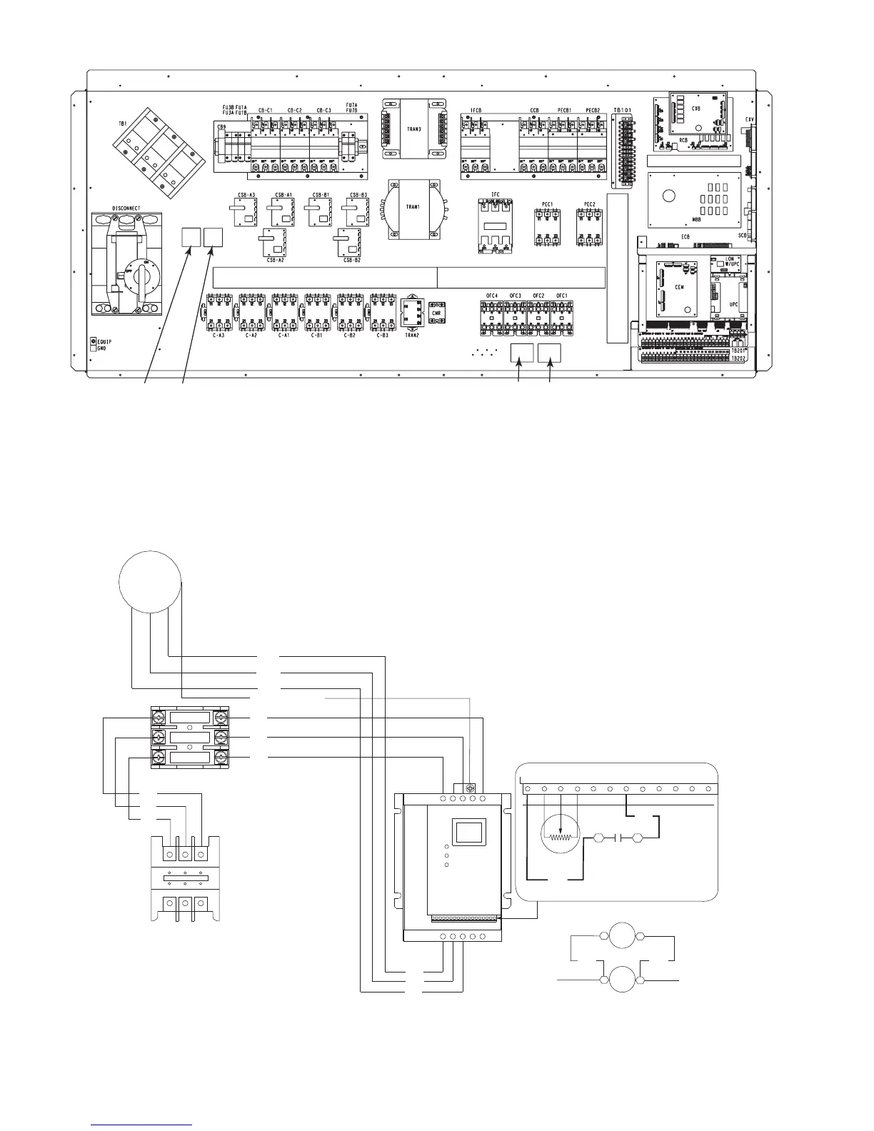
MMF-A
MMF-B
FR-A
FR-B
Fig. 7 — 48/50P Control Box Details
LEGEND
FR
—
F
an R
ela
y
MMF
—
Motormaster V Fuse Blo
c
k
a48-8565
OFM-1 (030,035,050-060)
OFM-3 (040)
MMV
-A
L1
L2
L3
T1
T2
T3
B-
B+
BLK
BLK
BLU
YEL
1
2
5
6
11
12
2
14
13A
13B
13C
15
5
9
MMPT
230-3-60 SHOWN.
REFER TO T
ABLE 4
FOR
AL
TERNA
TE VOL
T
AGE
CONNECTIONS
FR-A
OFC1
13
14
C1
C2
ADD F
AN RELA
Y (FR)
IN P
ARALLEL WITH OFC1
CCB
MM-F
BLU
YEL
A
B
C
TB
BLU
RED
BLK
GRN/YEL, DRAIN
RED
BLK
BLU
RED
BLK
GR
Y
WHT
11
12
13
22
23
21
FR-A
Fig. 8 — Motormaster
®
V Accessory Wiring — 48/50P030-
060 Units
LEGEND
CCB
—
Control Ci
rcuit
Break
er
FR
—
F
an Rela
y
MM-F
—
Motormaster V Fuse
Bloc
k
MMPT
—
Motor
master Pressure T
r
ansducer
MMV
—
Motormaster V Co
ntrol
OFC
—
Outdoor-Fan Contactor
OFM
—
Outdoor-F
an Motor
TB
—
T
er
minal Block
NOTE: Wire colors for MMPT
:
2 — BLACK (A)
5 — GREEN (C)
6 — RED (B)
a48-8566
7
9
Table of Contents
Table of Contents
1
Safety Considerations
1
Installation Instructions
1
General
1
Component List
2
Installation
3
Pre-Installation
3
Step 1 - Install Field-Fabricated Wind Baffles
3
Control
5
MMV Control Mounting 48/50P040 Units
7
48/50P Control Box Details
8
Accessory Wiring 48/50P030-060 Units
8
MMV Control Mounting 48/50P090/100 Units
11
Step 2 - Mounting and Electrical Connections Step 3 - Configure Motormaster V Control
11
Step 4 - Test Motormaster V Control
11
Start-Up
11
Drive Programming
13
Troubleshooting
13
Program Parameters for Operating Mode
14
Fault Codes
15
4
Based on 1 rating
Ask a question
Give review
Questions and Answers:
Need help?
Do you have a question about the Carrier MOTORMASTER 48/50P3 and is the answer not in the manual?
Ask a question
Carrier MOTORMASTER 48/50P3 Specifications
General
Brand
Carrier
Model
MOTORMASTER 48/50P3
Category
Air Conditioner
Language
English
Related product manuals
Carrier MODU-PAC 50DF
37 pages
Carrier Moduline 37HS Series
32 pages
WALL MOUNTED AIR CONDITIONER
8 pages
Carrier 38CK(M)
6 pages
Carrier MMK-AP0073H2UL
30 pages
Carrier MMK-AP0093H2UL
30 pages
Carrier MMY-MAP0724FT9UL
288 pages
Carrier MMY-MAP0964FT6UL
288 pages
Carrier MMY-MAP0964FT9UL
288 pages
Carrier MMY-MAP1204FT9UL
288 pages
Carrier MPPDB-12CRN7-QB6G1
19 pages
Carrier MPPDA-09CRN7-QB6G1
19 pages

 Loading...


