5
Humidity sensors for the air conditioned space
This controls room humidity. It is an optional sensor of the 0-
10 V d.c. or 2-10 V d.c. type.
Air quality sensor
This controls room air quality. It is an optional sensor of the 0-
10 V d.c. type.
Outdoor air enthalpy sensor
This optional sensor delivers a make-break signal depending on
the value for outdoor air heat content (enthalpy). The enthalpy
setpoint has to be adjusted on the sensor itself. If the enthalpy
value is high (closed signal) the economiser is disabled and
lowered to its minimum setting.
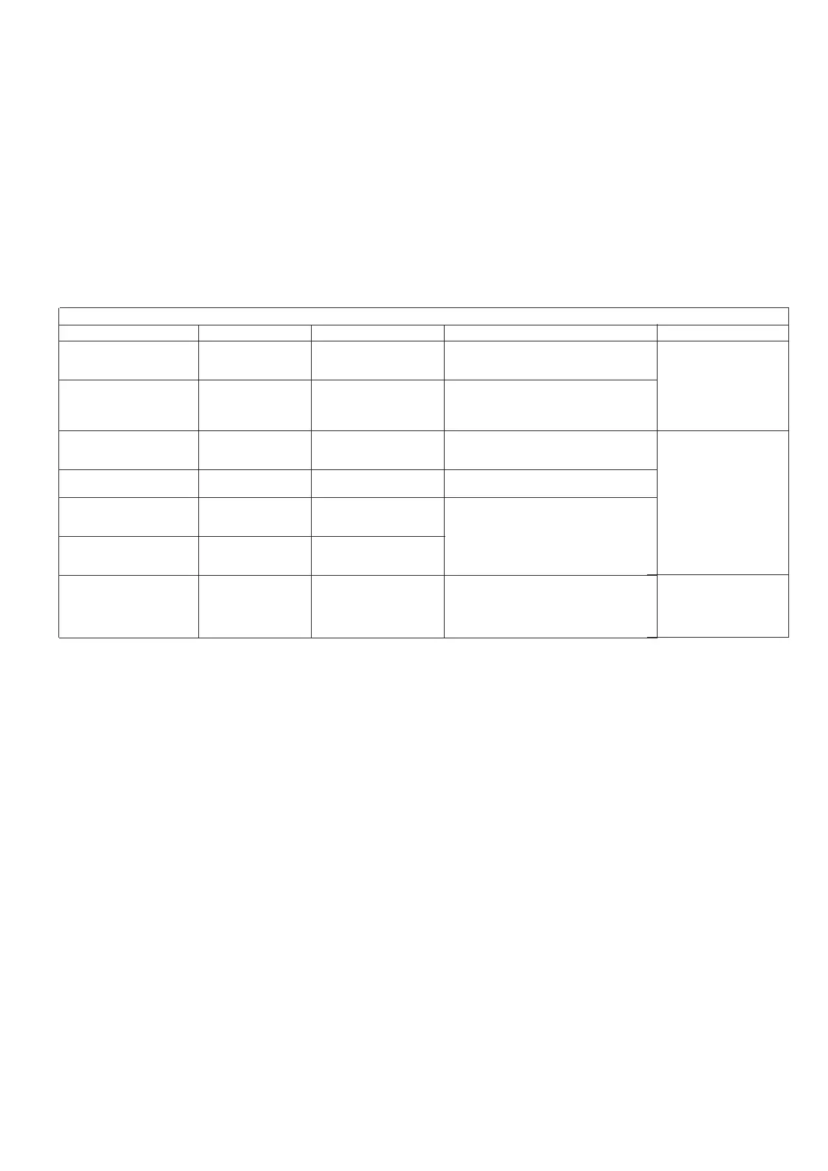
3.5 - Connections without thermostat input
The contacts below are available at the user's terminal block on
the NRCP-BASE board (see Fig. 1). Some of them can only be
used if the unit operates in remote operating type (rEM). The
following table summarises the connections at the user’s
terminal block.
Description
Alarm relay output
circuit A
Alarm relay output
circuit B
Contact 1:
start/stop
Contact 2:
demand limit selection
Contact 3:
setpoint selection 1
Contact 4:
setpoint selection 2
Connection to CCN
Connector/channel
J3 / CH24
J3 / CH24
J4 / CH8
J4 / CH9
J4 / CH10
J4 / CH11a
J12
Board
Master NRCP-BASE
Slave NRCP-BASE
Master NRCP-BASE
Master NRCP-BASE
Master NRCP-BASE
Master NRCP-BASE
Master NRCP-BASE
Remarks
Indicates alarms, circuit A
Indicates alarms, circuit B
This contact is used for unit start/stop
control. It is only taken into account if the unit
is under remote operation control (rEM).
This contact is used for unit demand limit
selection.
These contacts are used for setpoint
selection.
They are only taken into account if the unit is
in remote control operating type (rEM).
Note: Contact CH-11b must be bridged.
An RS-485 bus is used for connection to the
CCN.
- Pin +: signal +
- Pin G: ground
- Pin -: signal −
Remarks
Volt-free contact 24 V a.c.
48 V d.c. max, 20 V a.c. or
V d.c., 3 A max, 80 mA
min, external power supply.
Connector: 4 pin WAGO
734-168 pitch 3.5; One per
board needed.
24 V a.c., 20 mA
Connector: 8 pin Wago 734-
168, pitch 3.5
Connector: 3 pin Wago 231-
304/026000, pitch 5.08
UNIT WITHOUT THERMOSTAT
 Loading...