6
3.6 - Connections with thermostat input
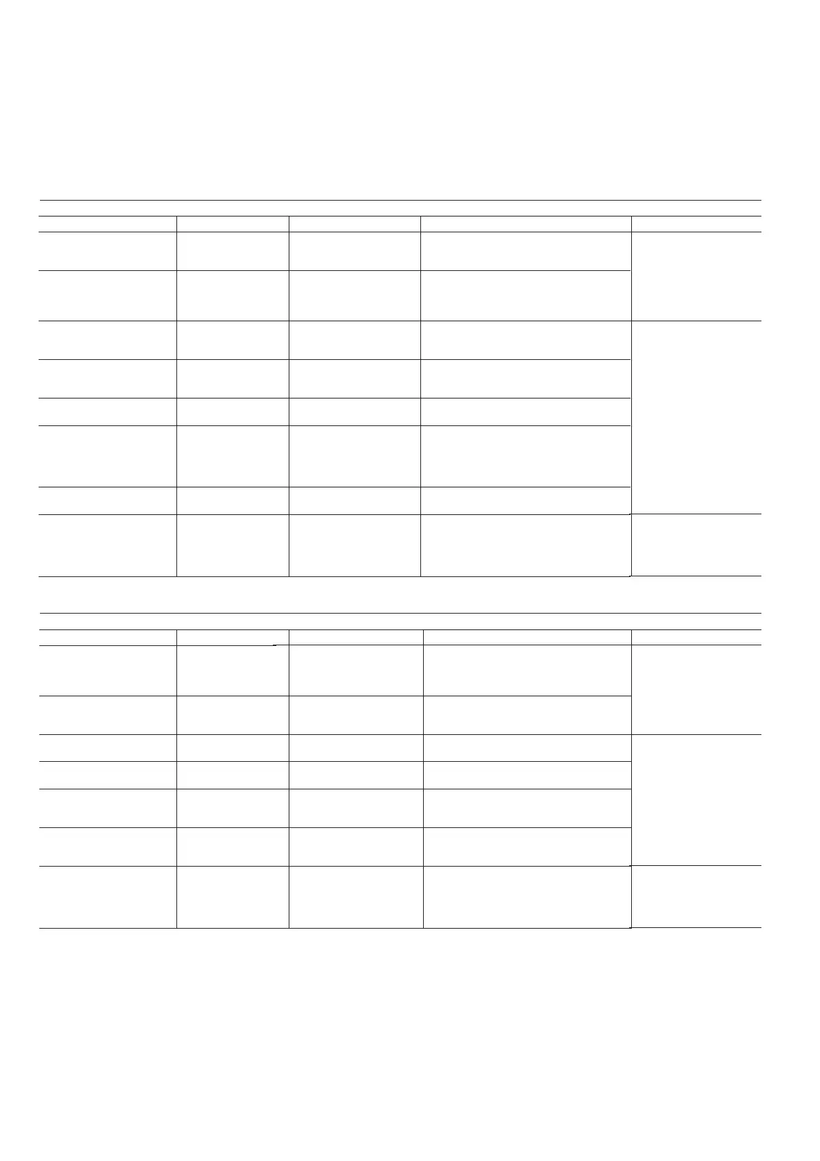
The contacts below are available at the user's terminal block on
the NRCP-BASE board (see Fig. 1). Some of them can only be
used if the unit operates in thermostat operating type (tStA).
The following table summarises the connections at the
thermostat terminal block.
Description
Alarm relay output
circuit A
Alarm relay output
circuit B
Contact 1:
contact G
Contact 2:
contact Y1_W2 (Y1 if
Y1_W2 not present)
Contact 3:
contact W_W1
Contact 4:
contact O_W2
Contact 5:
contact Y_Y2
Connection to CCN
Connector/channel
J3 / CH24
J3 / CH24
J4 / CH8
J4 / CH9
J4 / CH10
J4 / CH11a
J4 / CH9
J12
Board
Master NRCP-BASE
Slave
NRCP-BASE
Master NRCP-BASE
Master NRCP-BASE
Master NRCP-BASE
Master NRCP-BASE
Slave NRCP-BASE
Master NRCP-BASE
Remarks
Indicates alarms, circuit A
Indicates alarms, circuit B
This contact is used for unit start/stop
control.
This contact is used to control a unit
compressor.
This contact is used to control an additional
unit heating stage.
This contact is used to control an additional
unit heating stage in cooling only units or for
cooling/heating mode selection in reversible
units.
Note: Contact CH-11b must be bridged.
This contact is used to control a unit
compressor.
An RS-485 bus is used for connection to the
CCN.
- Pin +: signal +
- Pin G: ground
- Pin -: signal −
Remarks
Volt-free contact 24 V a.c.
48 V d.c. max, 20 V a.c. or
V d.c., 3 A max, 80 mA
min, external power supply.
Connector: 4 pin WAGO
734-168 pitch 3.5; One per
board needed.
24 V a.c., 20 mA
Connector: 8 pin Wago
734-168, pitch 3.5; One per
board needed.
Connector: 3 pin Wago 231-
304/026000, pitch 5.08
UNIT WITH THERMOSTAT FOR ANY UNIT TYPE EXCEPT REVERSIBLE UNITS WITH ONE COMPRESSOR
Description
Alarm relay output
circuit A
Contact 1:
contact G
Contact 2:
contact Y_Y2
Contact 3:
contact W_W1
Contact 4:
contact O_W2
Contact 5:
contact Y1_W2 (Y1 if
Y1_W2 not present)
Connection to CCN
Connector/channel
J3 / CH24
J4 / CH8
J4 / CH9
J4 / CH10
J4 / CH11a
J4 / CH9
J12
Board
Master NRCP-BASE
Master NRCP-BASE
Master NRCP-BASE
Master NRCP-BASE
Master NRCP-BASE
Slave NRCP-BASE
Master NRCP-BASE
Remarks
Indicates alarms, circuit A
This contact is used for unit start/stop
control.
This contact is used to control a unit
compressor.
This contact is used to control an additional
unit heating stage.
This contact is used for cooling/heating
mode selection.
Note: Contact CH-11b must be bridged.
This contact is used to control an additional
unit heating stage.
An RS-485 bus is used for connection to the
CCN.
- Pin +: signal +
- Pin G: ground
- Pin -: signal −
Remarks
Volt-free contact 24 V a.c.
48 V d.c. max, 20 V a.c. or
V d.c., 3 A max, 80 mA min,
external power supply.
Connector: 4 pin WAGO
734-168 pitch 3.5; One per
board needed.
24 V a.c., 20 mA
Connector: 8 pin Wago 734-
168, pitch 3.5; One per
board needed.
Connector: 3 pin Wago 231-
304/026000, pitch 5.08
REVERSIBLE UNIT WITH ONE COMPRESSOR WITH THERMOSTAT ONLY
 Loading...