For suspected electrical failures, check for loose or faulty electrical
connections or defective fan-motor capacitor. Fan motor is
equipped with thermal overload device in motor windings which
may open under adverse operating conditions. Allow time for
motor to cool so device can reset. Further checking of motor can
be done with an ohmmeter. Set scale onRX1position, check for
continuity between 3 leads. Replace motors that show an open
circuit in any of the windings. Place 1 lead of ohmmeter on each
motor lead. At same time, place other ohmmeter lead on motor
case (ground). Replace any motor that shows resistance to ground,
signs of arcing, burning, or overheating.
Step 11—Service Alarm Control Board
NOTE: If the proper night-setback thermostat is not used, the
service-alarm control will work, but there will be no light
indication on thermostat.
The service-alarm control provides immediate warning when
outdoor heat pump requires servicing. It turns on indoor
thermostat-malfunction light if compressor does not operate for
either heating or cooling. This enables owner to obtain timely
heat-pump service during heating season, reducing supplementary
electric heat costs, and during cooling season, reducing period of
heat discomfort.
The service alarm is an accessory device. Service alarm locks out
compressor under certain adverse operating conditions. System is
manually reset by shutting it off at thermostat subbase, then
turning it back on. If adverse condition is corrected, system
restarts.
One example of an adverse condition would be a system located in
a desert climate where high operating temperatures may cause
system to shut down on the high-pressure switch or on the
compressor internal overload.
Connect service alarm to outdoor-unit control-circuit-terminal
board. (See Fig. 25 and wiring diagram on unit.)
Connect all field line-power wires to unit in usual manner. Route
1 field line-power supply wire through metallic loop on bottom of
service alarm then to normal unit connection. Units with RLA of
less than 14 amps will require 2 passes through the metallic loop.
Refer to Fig. 25 or 26 for wiring connections for service alarm or
service alarm with solid-state cycle-protector accessories, when
used.
NOTE: The wire from the X terminal on the service alarm to L on
the outdoor terminal board, indoor terminal board, and thermostat
subbase is field supplied and wired when using defrost controls
HK32FA003 or HK32FA006. When defrost control CES0110063
or CES0130024 is used, field-supplied wire from X terminal on
service alarm to L on indoor thermostat subbase is required.
Service alarm requires 2 inputs.
1. It must sense a 24v input from thermostat. As thermostat calls
for heating or cooling, it supplies 24v to service alarm device.
2. A current transformer (or induction loop) similar to a
clamp-on ammeter senses current draw in the compressor
lead. Induction loop must sense a minimum current draw
when thermostat is calling for heating or cooling.
NOTE: On a single-phase compressor, induction loop senses
current in common leg. On a 3-phase compressor, induction loop
senses current in any 1 of the phases.
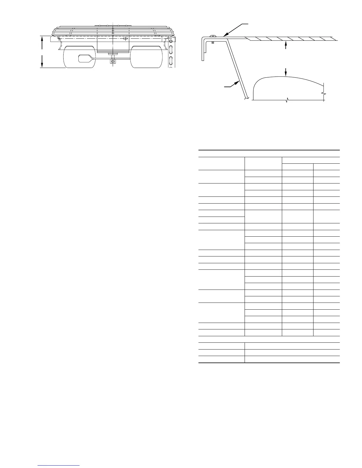
BASKET TOP
A
A91428
TOP COVER
FAN
ORIFICE
FAN BLADE
3 IN. SMALL & MEDIUM BASE UNITS
4 IN. LARGE BASE UNIT
FROM DISCHARGE LOUVER
TO TOP OF FAN BLADE
STAR BURST TOP
A88347
Fig. 24—Fan Position
Table 13—Fan Position
SILENCER SYSTEM™ AND BASKET TOP
Fan Motor
Part No.
Fan Blade
Part No.
Dimension A (In.)
Brookside Revcor
HC29GE208
LA01EB023 4-5/32 –
LA01EC019 5-1/8 –
HC31GE230/231
LA01EA026 4-5/8 –
LA01RA015 4-7/8 4-5/8
HC33GE208 LA01EW049 5-1/4 –
HC33GE232 LA01RA015 4-29/32 4-17/32
HC34GE231
LA01RA015 5-5/32 4-25/32
HC34GE460
HC35GE208 LA01EW048 4-15/16 –
HC35GE232
LA01EA025 5-7/8 –
LA01RA024 5-11/32 5-3/32
LA01RA026 5-9/16 4-11/16
HC37GE208 LA01EA025 6-1/8 6-1/8
HC37GE230 LA01EW042 6-5/32 6-1/8
HC38GE221 LA01EA031 7-25/32 –
HC39GE232
LA01EC018 5-11/16 –
LA01RA026 5-1/2 4-3/4
LA01EA036 5-9/16 –
HC39GE234
LA01EA024 5-3/32 4-27/32
LA01EC018 5-1/2 –
HC39GE461
LA01EA036 6-1/16 –
LA01EC018 6-1/4 –
LA01RA026 6-1/16 5-7/32
HC40GE230 LA01EA024 5-9/32 5-11/32
HC40GE461 LA01EA024 5-27/32 5-19/32
BASEPAN DIMENSIONS FOR STAR BURST TOP (IN.)
Small 22-1/2 x 26-3/16
Medium 30x33
Large 38-5/8 x 42-1/16
23
 Loading...