Step 3—Install Thermostat
Before installing thermostat, turn off all power to unit. There
may be more than 1 power disconnect. Electrical shock can
cause personal injury or death.
1. Turn OFF all power to unit.
2. If an existing thermostat is being replaced:
a. Remove existing thermostat from wall.
b. Disconnect wires from existing thermostat, 1 at a time. Be
careful not to allow wires to fall back into the wall.
c. As each wire is disconnected, record wire color and
terminal marking.
d. Discard or recycle old thermostat.
NOTE: Mercury is a hazardous waste and MUST be disposed of
properly.
3. Open thermostat rear door (mounting base) to expose mount-
ing holes. The base can be removed to simplify mounting.
Snap apart carefully at hinge to separate mounting base from
remainder of thermostat.
4. Route thermostat wires through large hole in mounting base.
Level mounting base against wall (for aesthetic value
only—thermostat need not be leveled for proper operation)
and mark wall through 2 mounting holes.
5. Drill two 3/16-in. mounting holes in wall where marked.
6. Secure mounting base to wall with 2 anchors and screws
provided, (additional anchoring holes available for more
secure mounting if needed) making sure all wires extend
through hole in mounting base.
7. Adjust length and routing of each wire to reach proper
terminal and connector block on mounting base with 1/4 in. of
extra wire. Strip only 1/4 in. of insulation from each wire to
prevent adjacent wires from shorting together when con-
nected.
8. Match and connect equipment wires to proper terminals of the
connector blocks. (See Table 1 and Fig. 2 through 24.) Both R
and C must be connected for proper thermostat operation.
Improper wiring or installation may damage the thermostat.
Check to make sure wiring is correct before proceeding with
installation or turning on unit.
9. Push any excess wire into wall and against mounting base.
Seal hole in wall to prevent air leaks. Leaks can affect
operation.
10. Snap hinge back together.
11. Close thermostat assembly making sure pins on back of circuit
board align with sockets in connector.
12. Turn ON power to unit.
On power up, LCD readout will display AC, HP, A2, or H2
depending on the thermostat model and jumper status. See "Power
On Check" under "Operational Information" on page 11 for
explanation.
Step 4—Set Thermostat Configuration
Configuration options, like the R19 configuration jumper are
intended to be selected at installation and are normally not
modified by the homeowner. These options are not discussed in the
Homeowner’s Guide and therefore must be made as part of the
installation. A special procedure allows entry into the configura-
tion mode. The thermostat will automatically exit this mode if no
button is pressed for 3 minutes. While in the configuration mode,
up to 8 option choices can be made:
Option 01:"Anticipator" adjustment
Option 02: Clean filter timer adjustment
Option 03: Fahrenheit or Celsius operation
Option 04: Enable fan (G) on with any heat (W)
Option 07: Enable zoning
Option 08: Auxiliary heat lockout temperature adjustment
Option 13: Room temperature offset adjustment
Option 15: Enable AUTO mode
An explanation for each of these and how to enter the configura-
tion mode follows.
To enter the configuration mode:
Press and hold the FAN button for approximately 10 sec until
room temperature disappears and display reads "01". You are now
in the configuration mode.
NOTE: If the FAN button is pressed again or if no button is
pressed for 3 min, the thermostat will exit the configuration mode
and return to normal operation. To re-enter the configuration
mode, the FAN button must be pressed and held for 10 sec again.
While in configuration mode:
The display is used to show both the option number and the
selection choice within that option.
OPTION 1—ANTICIPATOR ADJUSTMENT
This adjustment controls the sensitivity and cycle rate of the
thermostat. Higher numbers decrease the sensitivity and slow the
cycle rate. Lower numbers increase sensitivity and increase cycle
rate. However, a limiting feature will not allow more than 4
equipment cycles per hr, regardless of setting. Values can range
from 1 to 9. Factory default setting is 3. This default selection will
provide optimum performance in nearly all installations. Try it
first. Do not change setting unless there is evidence of need to do
so.
Unlike conventional anticipators, this setting is not to be deter-
mined by current draw. There is no need to measure, know, or
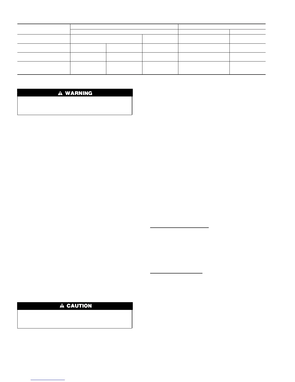
Table 1—Model Selection and Wiring Diagram Chart
OUTDOOR UNIT
AIR CONDITIONER HEAT PUMP
1 Speed 2 Speed 1 Speed 2 Speed
1-Stage
Furnace
Model AC
See Fig. 2
Model 2S
See Fig. 8
Requires
Dual Fuel Thermostat
Model 2S
See Fig. 11
2-Stage
Furnace
Model AC
See Fig. 3
Model HP
See Fig. 5
Model 2S
See Fig. 9
Requires
Dual Fuel Thermostat
Model 2S
See Fig. 12
Typical Fan Coil
Model AC
See Fig. 4
Model HP
See Fig. 6
Model 2S
See Fig. 10
Model HP
See Fig. 7
Model 2S
See Fig. 13
Variable-Speed
Fan Coil
(FK4C, FV4A, 40FKA)
Model AC
See Fig. 14
Model HP
See Fig. 15
Model 2S
See Fig. 16
Model HP
See Fig. 17
Model 2S
See Fig. 18
2
→
→
 Loading...