6871082-R2 15
ADJUSTING PAD CAMBER
STANDARD (SHIMMED) DESIGN
CC0012.eps
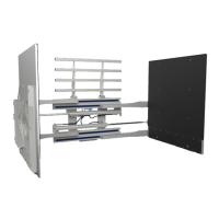
4 Loosen the contact pad capscrews and nuts.
NOTE: It is not necessary to remove the capscrews
and nuts to insert the shims.
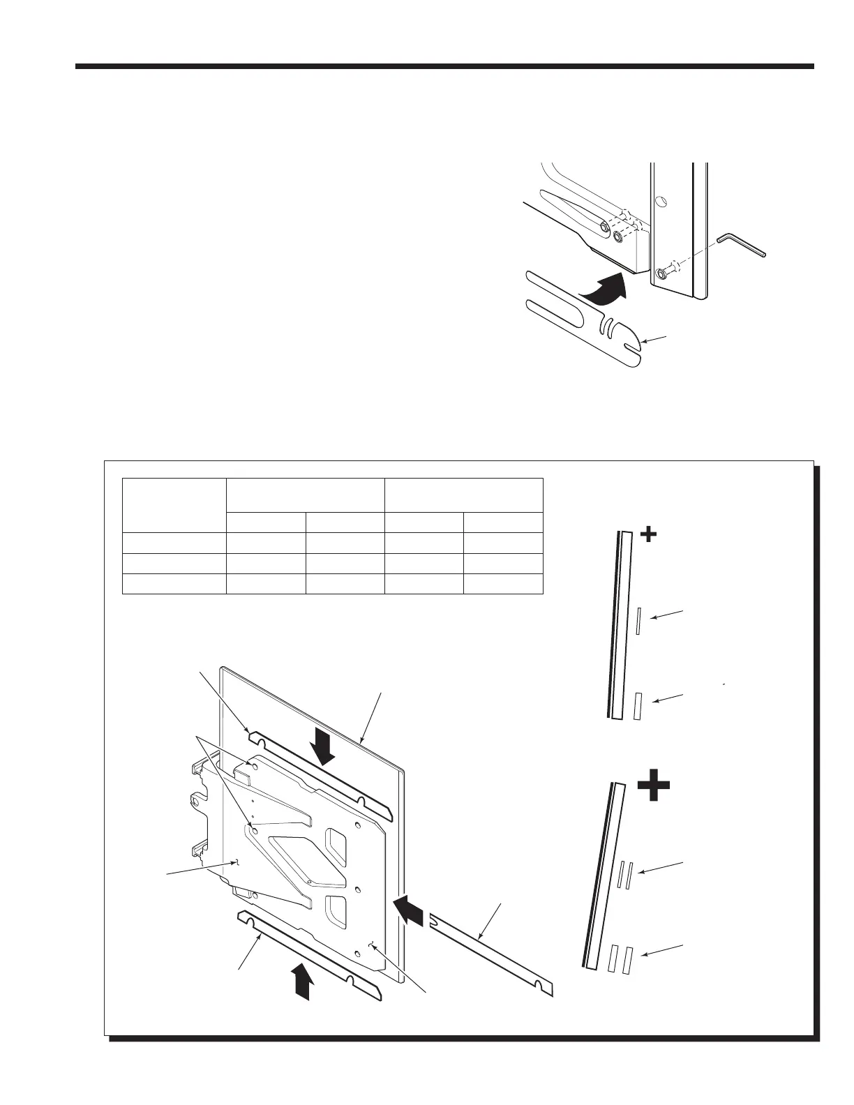
5 Install shims as required.
• Positive Camber – Install shims at the bottom and
middle of the pad to increase clamp force at the
bottom of the load.
NOTE: This will increase the clamp force
percentages on the lower spindles readout of the
4-Point Force Distribution Tester.
• Negative Camber – Install shims at the top and
middle of the pad to decrease clamp force at the
bottom of the load.
NOTE: This will increase the clamp force
percentages on the upper spindles readout of the
4-Point Force Distribution Tester.
CAUTION: Use an equal number of shims on each
contact pad. Pad camber must be the same on both
sides of the attachment for proper load handling.
"U" Shim
4
4
5
5
5
5
Top Shim
Contact Pad
Pad
Capscrews
and Nuts
Arm
Bottom Shim
Stabilizer
Middle Shim
FOR MINIMUM
POSITIVE CAMBER:
FOR MAXIMUM
POSITIVE CAMBER:
Middle Shim:
Long Shim – One Each
0.06 in. (1.6 mm)
"U" Shim –
One Each, 2 Places
0.04 in. (1 mm)
Middle Shim:
Long Shim – Two Each
0.06 in. (1.6 mm)
"U" Shim –
Two Each, 2 Places
0.04 in. (1 mm)
Bottom Shim:
Long Shim – One Each
0.125 in. (3.2 mm)
"U" Shim –
One Each, 2 Places
0.08 in. (2 mm)
Bottom Shim:
Long Shim – Two Each
0.125 in. (3.2 mm)
"U" Shim –
Two Each, 2 Places
0.08 in. (2 mm)
Contact Pad
Camber
Clamp Force Change @
Maximum Shimming ◆
Clamp Force
Distribution
Upper Lower Upper Lower
Neutral ▲
— — 35% 65%
Negative +10% –10% 45% 55%
Positive –10% +10% 25% 75%
▲ Shimmed equally in all locations.
◆ Camber based on 12 mm total shims negative or positive position.
 Loading...