6871082-R216
ADJUSTING PAD CAMBER
FLEXIBLE (ADJUSTA-BLOCK) DESIGN
The following procedure is performed on attachments
with flexible (ADJUSTA-BLOCK) design for contact pad
and stabilizer. This procedure can be performed with the
attachment mounted on the truck. A Cascade 4-Point
Force Distribution Tester is required for this procedure.
IMPORTANT: Clamp circuit pressure should be adjusted,
if required, prior to adjusting the pad camber. Refer to
Installation Step 11 (page 7).
1 Extend the arms to the most common load width.
Lower the contact pads to just above the floor.
2 Position the tester between the contact pads. Adjust
the tester spindle locations to be perpendicular to
the contact pad surfaces and to the desired position
based on the type of product being handled.
3 Clamp on the tester and hold activated for 5 seconds.
4 The tester will display clamp force and percentage of
clamp force for each spindle location and total clamp
force (sum of force of the four spindles).
5 Clamp force distribution should be within the desired
percentages and tolerances.
If the tolerance difference is greater than allowable
tolerance difference, the contact pads require pivot
block adjustment. Continue to Step 6 for adjustment.
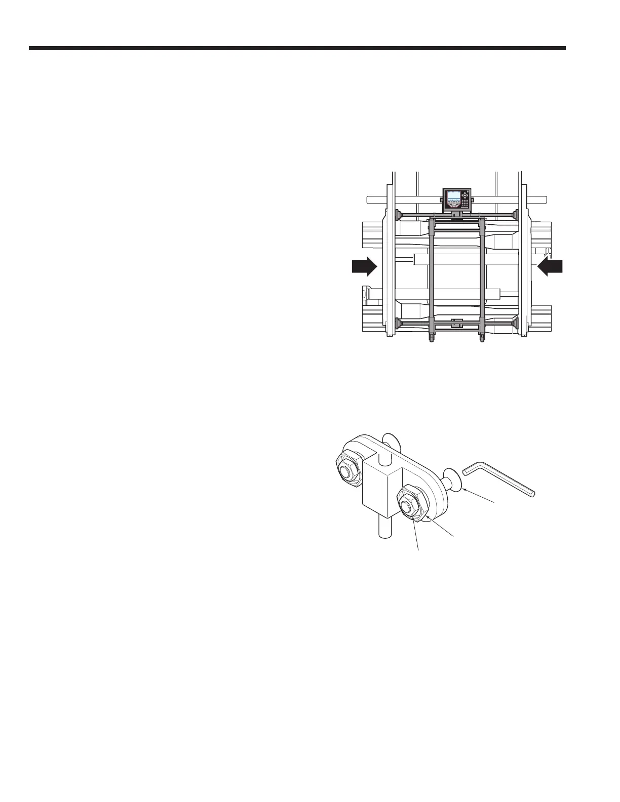
Locking Nut
Capscrew
Collar
8mm
Allen Wrench
ADJUSTA-BLOCK Assembly
6 Clamp force distribution can be changed at the
ADJUSTA-BLOCK locations on the right hand contact
pad. Tune as follows:
• Loosen the locking nuts 3 turns. Use an 0.31 in.
(8 mm) allen wrench to hold the capscrews.
• Adjust the collar using a 1.25 in. (32 mm) socket.
Turn the collar CW to increase clamp force, CCW to
decrease clamp force. One full turn of the collar is
approximately 0.08 in. (2 mm) linear travel or 10% of
force.
Follow adjustment sequence, Step 7.
Procedure continued on the following page.
3
 Loading...