- 8 -
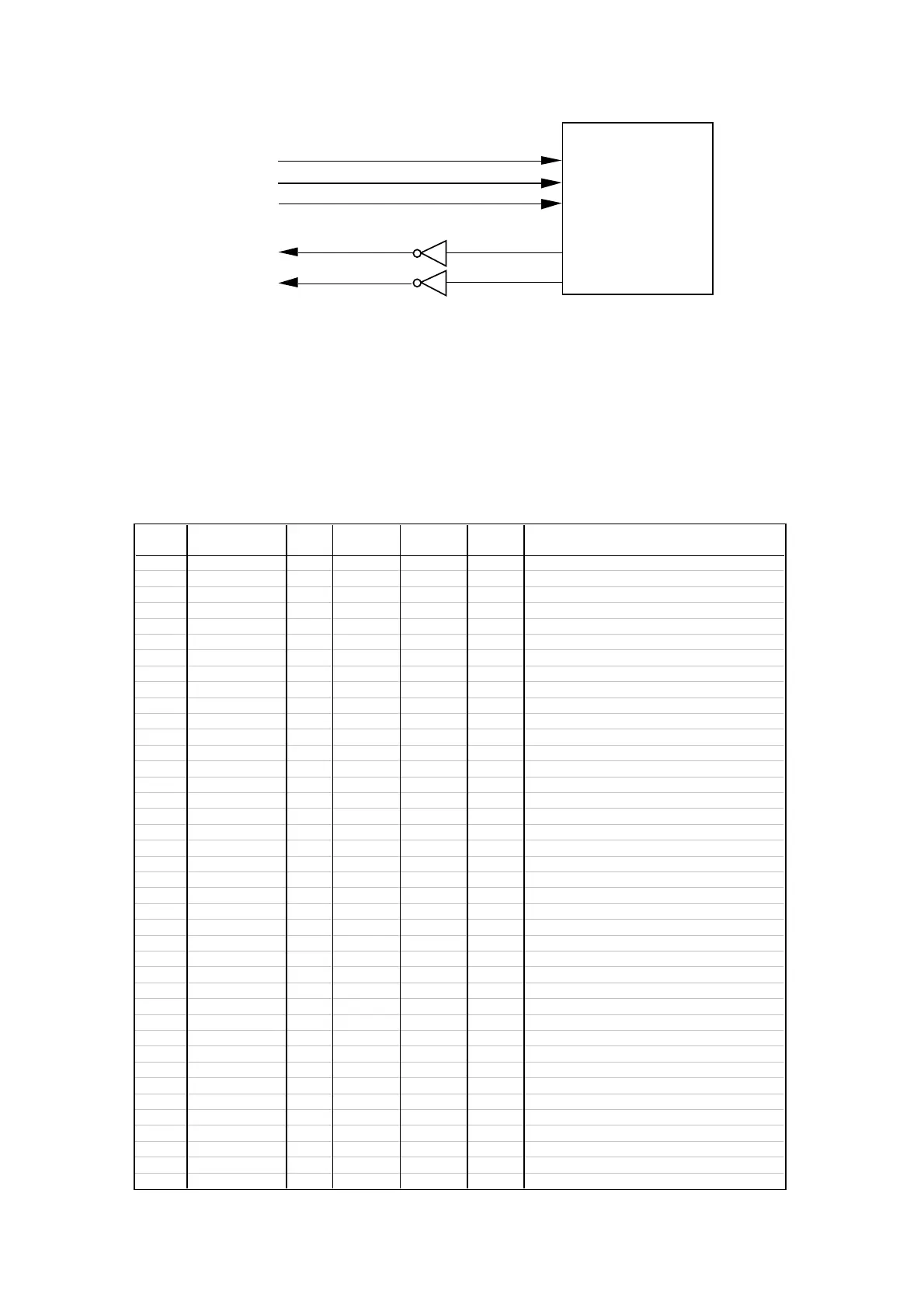
6-4. Printer drive circuit
When the CPU start printing, CPU send MD signal to rotate motor unit.
Then the printer send back the RP(reset pulse),PT and PT (Timing pulse) to CPU.
After CPU receive RP,PT andPT, CPU knows the position of printin wheel.
And then, CPU send HD signal to operate the printing magnet when the character selected.
The CPU counts the TP signal to select the character.
6-5. Pin description (CPU uPD78042AGF)
CPU
Pin No.44
Pin No.45
Pin No.47
Pin No.62
Pin No.63
RP
Pt
PT
MD
HD
Printer M42
Pin No. Signal In/Out
Mode SW
REG
Mode SW
OFF
AC cord
Plug off
Description
1 P94/FIP6 Out Pulse -24V L Display digit signal DG7
2 P93/FIP5 Out Pulse -24V L Display digit signal DG6
3 P92/FIP4 Out Pulse -24V L Display digit signal DG5
4 P91/FIP3 Out Pulse -24V L Display digit signal DG4
5 P90/FIP2 Out Pulse -24V L Display digit signal DG3
6 P81/FIP1 Out Pulse -24V L Display digit signal DG2
7 P80/FIP0 Out Pulse -24V L Display digit signal DG1
8 VDD - +5V +5V +5V VDD terminal
9 P27/SCK0 In/Out - - - Not used
10 P26/SO0/SB1 In/Out - - - Not used
11 P25/SI0/SB0 In/Out - - - Not used
12 P24/BUSY In/Out - - - Not used
13 P23/STB Out H H H Strobe signal for AVREF
14 P22/SCK1 Out L H H SK signal for EEPROM
15 P21/SO1 Out L H H DI signal for EEPROM
16 P20/SI1 In H H H DO signal for EEPROM
17 RESET In H H H Reset signal
18 P74 Out H H L Drawer open signal
19 P73 Out L H H Common signal for PAD condition
20 AVSS - GND GND GND GND for AD converter
21 P17/ANI7 In GND GND GND GND
22 P16/ANI6 In GND GND GND GND
23 P15/ANI5 Out L L H Chip enable signal for EEPROM
24 P14/ANI4 In GND GND GND GND
25 P13/ANI3 In GND GND GND GND
26 P12/ANI2 In GND GND GND GND
27 P11/ANI1 In GND GND GND GND
28 P10/ANI0 In H H H Low battery detection terminal
29 AVDD - H H H Power for AD converter
30 AVREF In L L L Voltage for AD converter (VDD)
31 XT1 In Pulse Pulse Pulse Sub system clock
32 XT2 - Pulse Pulse Pulse Sub system clock
33 VSS - GND GND GND GND
34 X1 In Pulse L L Main system clock
35 X2 - Pulse H H Main system clock
36 P37 In L L L Mode switch position (OFF)
37 P36/BUZ Out L L L Buzzer signal
38 P35/PCL In L L L Mode switch position (Z)
39 P34/T12 In L L L Mode switch position (X)
40 P33/T11 In L L L Mode switch position (CAL)
 Loading...