— 8 —
LCD driver (HD44105H) : LSI201
LCD driver (HD44102CH) : LSI202
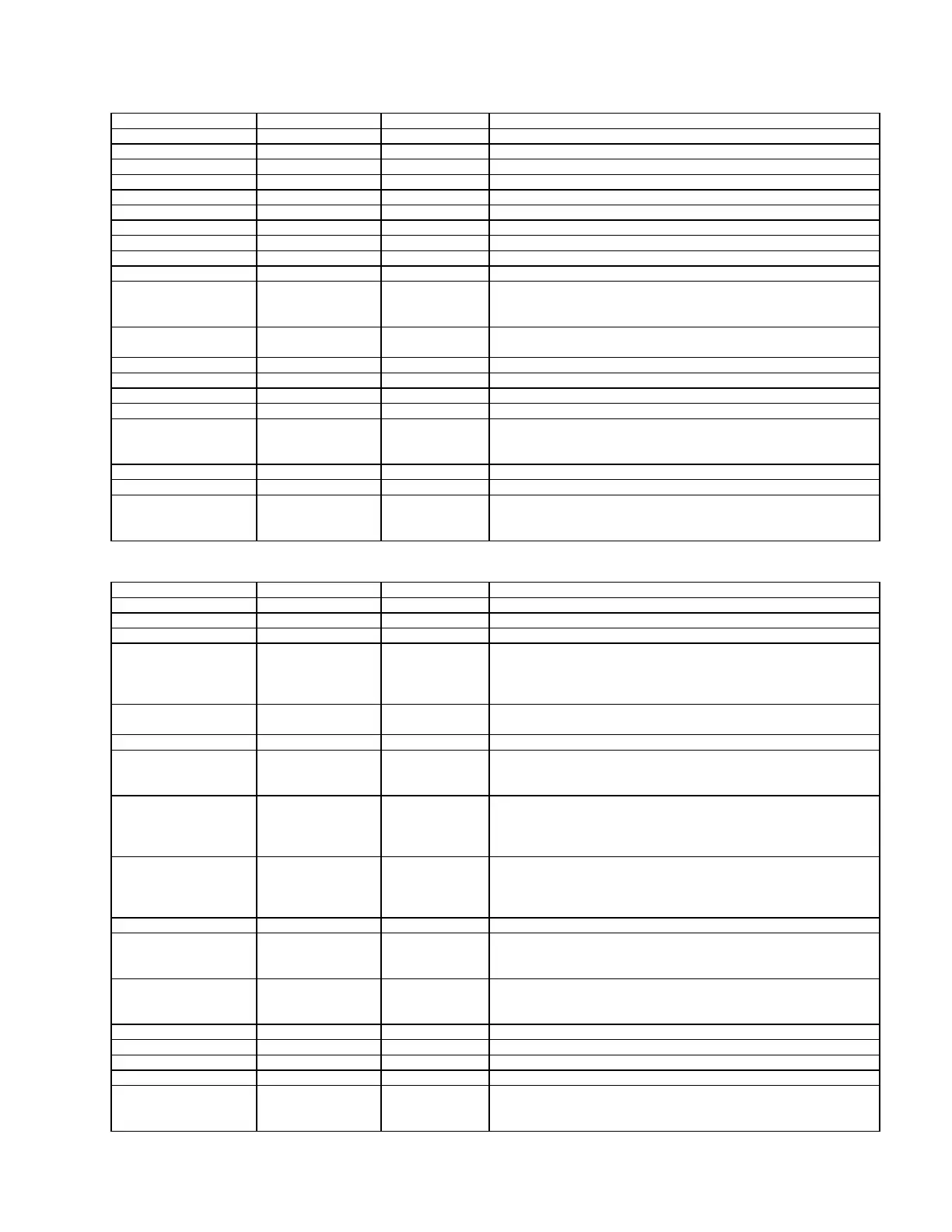
Table-3
Table-4
No Name I / O Function
1~12, 41~60 X1~X32 O LCD drive output
13 DL I / O I/O pin for 2 way shift register and shift data
14 GND Ground
15, 16 FS1, FS2 I Select frequency
17~19 DS1~DS3 I Select display duty
20 C Oscillator
21 R Oscillator
22 CR Oscillator
23 STB I Input pin for test use
24 SHL I 2 way shift register, select shift direction
25 M/S I
Master/slave switching
M/S=H : master mode
M/S= L : slave mode
26, 27 ø1, ø2 O
Output pin to HD44102CH operation clock. The
frequency is half the frequency of the oscillator.
28 FRM O Display synchronize signal (frame signal)
29 VCC +5V source
30, 32, 35 NC Not used
31 M I/O LCD drive alternating signal
33 CL I/O
Shift register shift clock
Output at master
Input at slave
34 DR I/O I/O pin for 2 way shift register and shift data
36 VEE Power source for LCD drive circuit. 0~+5.5V
37~40 V1~V4
LCD drive level power
V1, V2 : Selecting level
V3, V4 : No selecting level
No Name I / O Function
1~22, 24~40, 70~80 Y1~Y50 O LCD drive output signal
23, 62 NC Not used
41 VCC I +5V source
42 BS I
Bus select
BS=L : DB0~DB7 work at 8-bit
BS=H : DB4~DB7 are only active a 4-bit.
8-bit data is split in two and accessed in order.
43 RST I
Reset signal. Set RST signal to low level and display is
turned off.
44~46 CS1~CS3 I Chip select
47 E I
Enable
R/W=L : latches E fall DB0~DB7
R/W=H : E=H sends data to DB0~DB7
48 R/W I
Read/Write
R/W=H : Sends data to DB0~DB7 when E=H, CS2, 3=H
R/W=L : Receive from DB0~DB7 when CS2,3=H or
CS1=H
49 D/I I
Data/Instruction
D/I=H : Indicates that DB0~DB7 data is display data
D/I=L : Indicates that DB0~DB7 data is display control
data
50~57 DB0~DB7 I/O Data bus
58 FRM I
Display synchronize signal (frame signal)
When FRM=H, the 5-bit display line counter is reset, and
synchronizes the common signal and frame timing.
59 CL I
Display synchronize signal. Synchronizes with the rise
of the CL signal, and sends the liquid crystal signal for
the display data.
60, 61 ø1, ø2 2 phase clock for internal operation
63 M I Alternating signal for LCD drive output
64 GND Ground source
65 VEE Power source for LCD. 0~+5V.
66~69 V1~V4
Level power for LCD drive.
V1 / V2 : Selecting level.
V3 / V4 : No selecting level.
 Loading...