— 4 —
PRECAUTIONS
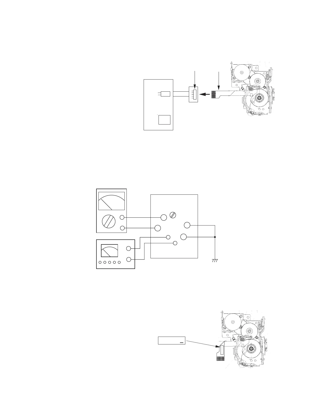
To prevent damage of the thermal head caused by static electricity when assembling the chassis ass'y into the
unit, the following steps must be followed;
1 : Turn the power switch off.
2 : Discharge the capacitor C18(2200µF) on the PCB L271-1.
3 : Connect the FPC of chassis ass'y into
a connector CN301 of PCB L271-2.
4 : Assemble the chassis ass'y.
5 : Turn the power switch on.
ADJUSTMENT
Adjustment of low battery detection circuit
To adjust the threshold voltage of the low battery detection circuit, the following steps must be followed;
1 : Apply 6.2V + 0.1V / -0V to the battery terminals.
2 : Ground check pads CP45 and CP46.
3 : Adjust a pot VR1 so that the voltage between CP1 and CP2 is 0V ± 10 mV.
Setting the thermal head rank
Set the thermal head rank with pads RNK1 and RNK2 on the PCB L271-1 according to the following conditions
when replacing the chassis ass'y or thermal head. The head rank is indicated on FPC as following figure-6.
Head rank A : RNK1=ON, RNK2=OFF
Head rank B : RNK1=OFF, RNK2=OFF
Head rank C : RNK1=ON, RNK2=ON
Head rank D : RNK1=OFF, RNK2=ON
Figure-5
Figure-6
FPC
PCB L271-1
PCB L271-2
CN301
C18
LSI1
Chassis ass'y
PCB-L271-1
+
-
Multi-meter
+
-
CP1
CP2
VR1
CP45
CP46
GND
Power supply
6.2V (+0.1 / -0 V)
BATT
+
BATT
-
Chassis ass'y
XXXXXXB
XXXXXXB
Head rank = B
Figure-4

 Loading...