5 . MAINTENANCE AND ADJUSTMENTS
5.31
Challenger MT500B EU
5
5.20.4 - Headlight adjustment
The headlights are adjusted by tightening or loosening the
three screws as required.
NOTE: Do not let your fingers come into direct contact
with the iodine bulbs.
Legend (Fig. 47)
A. Distance between the headlights and a wall or a
screen.
B. Height from the centre of the headlights to the ground.
C. Headlights centre to centre distance.
D. Height after adjustment.
5.20.4.1 - Headlight adjustment procedure
1. Position the tractor facing a wall or a screen 7.5m
away and on a level surface;
2. Draw a horizontal line, 1, on wall equal to height, B;
3. Draw two vertical lines on wall equal to width, C;
4. Draw a horizontal line, 2, according to D = (B x 0.1).
Adjust each headlight individually, by masking the
opposite light, and aligning the upper edge of the
lighted zone with the top of line 2.
5.20.5 - Xenon work headlights (optional)
Certain precautions must be taken when replacing bulbs on
models equipped with this option.
WARNING: The electrical connection
between headlight and light ballast is under
HIGH VOLTAGE and must not be discon-
nected. Before replacing the xenon bulb,
always switch headlights off and disconnect from the
power supply.
Never insert foreign objects or fingers into the bulb
holder.
- The light ballast is to be attached next to the head-
light. Install the headlight and light ballast in a way
that excludes a negative effect on the engine cooling
system.
- Make sure not to twist the power supply cable
between headlight and light ballast by more than 90°
and/or bend it by radius smaller than 20 mm.
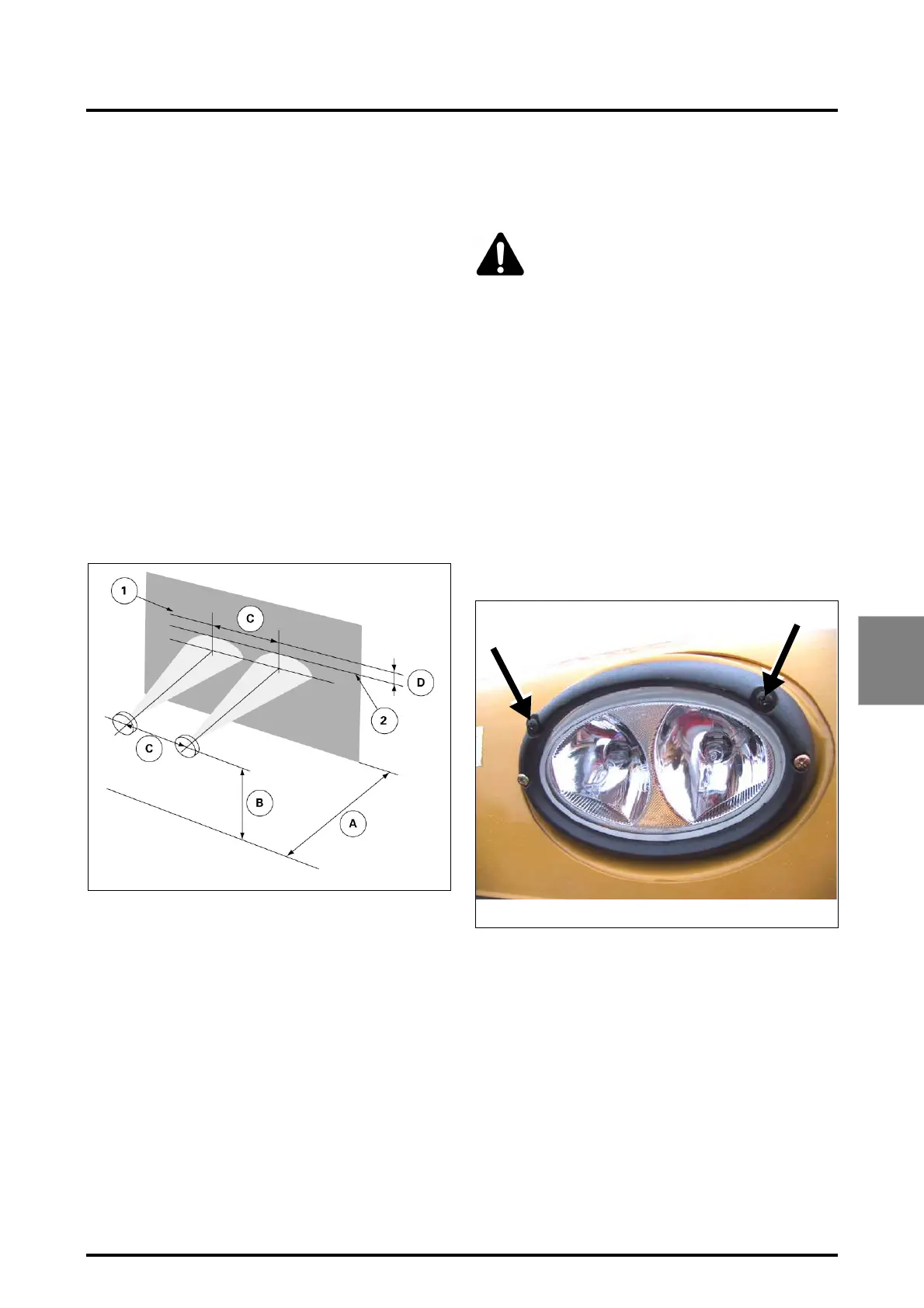
5.20.5.1 - Adjusting work headlights
The work headlights are adjusted by screwing the 2 screws
in or out as required.
Fig. 47
Z2-525-05-03
Fig. 48
CE-002-01-05
 Loading...