OMM-05-0509-page 4
2. Elevated Units:
Improper mounting of elevated blowers can cause vibration problems. The structure that the blower/motor assembly
will be mounted on must be strong enough to support at least 3 times the weight of the entire blower/motor assem-
bly. An insufficient support WILL CAUSE excessive vibration and lead to premature wheel and/or bearing
failures. Bracing of the support structure must be sufficient enough to prevent any side sway. The entire structure
should be welded at all connection joints to maintain constant alignment. If the blower will be sitting on some type of
vibration pads or mounts, follow the recommended mounting procedures supplied with the vibration elimination
equipment. BUT, the same procedure as outlined in Section II- Item A on page 3 must be followed.
THE IMPROPER DESIGN OF AN ELEVATED PLATFORM STRUCTURE COULD RESULT IN A RESONANT
CONDITION, AND CONSEQUENTLY, CAUSE A LIFE THREATENING, CATASTROPHIC,
STRUCTURAL FAILURE.
C. Duct Work Connections:
All duct connections to the blower should include flexible connectors between the ducting and the blower inlet and/or
discharge. This will eliminate distortion, noise and vibration from transmitting to the duct and building. The connec-
tors should be selected to handle the operating conditions for air volume and pressure that the blower will produce.
All ducting or accessories, added by the user, should be independently supported. DO NOT use the blower
assembly to support any additional weight. Inlet and/or discharge duct elbows should be located a minimum 2
blower wheel diameters from the blower. Any duct elbows located closer than 2 wheel diameters to the blower inlet
or discharge WILL reduce the air performance and blower efficiency. Any duct elbows near the blower discharge
should be in the same rotational direction as the blower rotation.
Non-Ducted Blower Inlet:
Any blower with no ducting on the inlet must have an inlet guard. The blower should be located so the blower inlet
is, at least, 1 wheel diameter away from any wall or bulkhead to eliminate a reduction in air flow.
Non-Ducted Blower Discharge:
Any blower with no ducting on the discharge must have a discharge guard.
D. Safety Guards:
Cincinnati Fan offers guards, as optional, to keep your blower in compliance with OSHA safety regulations. These
include inlet or discharge guards and any blowers built with high temperature construction includes a heat slinger
guard as standard. Since Arrangement 1 blowers are supplied without a motor, sheaves and belts, we cannot supply
a blower shaft or belt guard. It is the responsibility of the user to make sure this entire blower/motor unit will
meet all local, state and OSHA safety regulations after the entire assembly is completed.
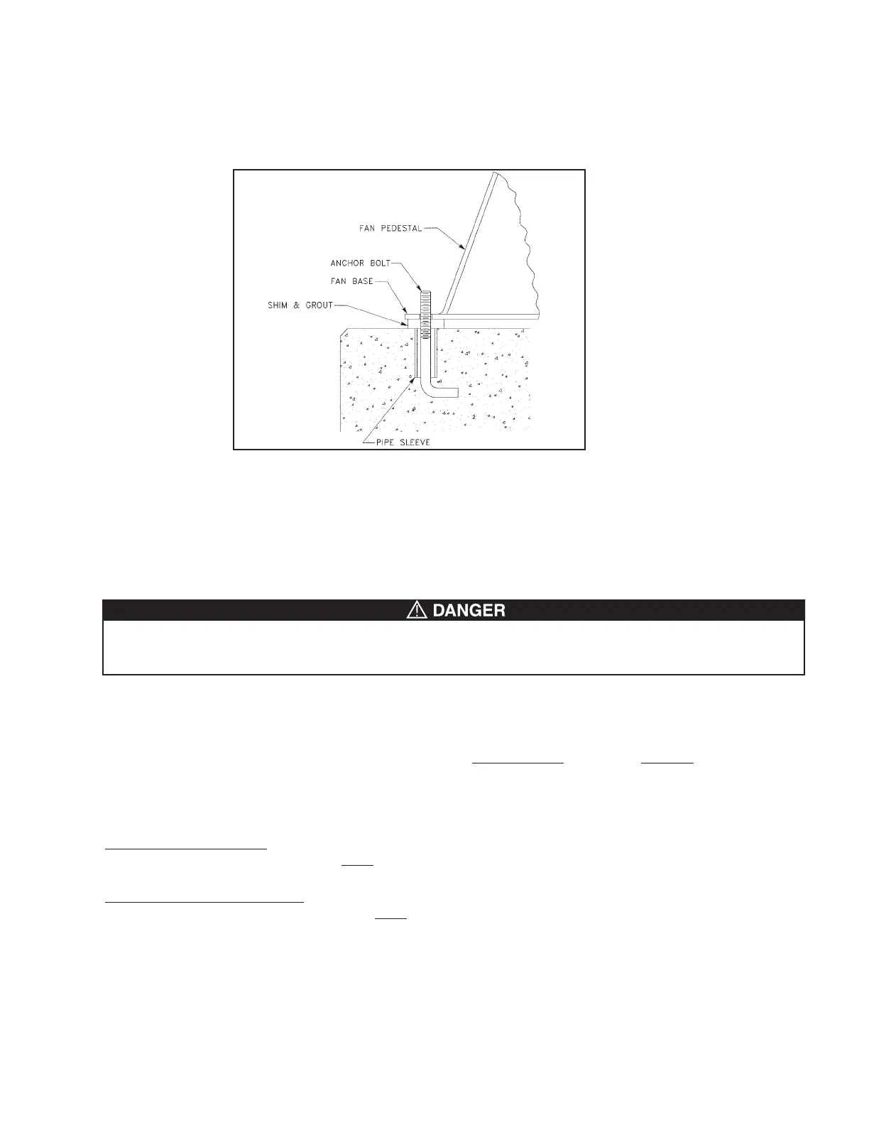
Fig. 1
The foundation should include anchor bolts such as shown in Fig. 1 below. Place the blower over the anchor bolts
and shim under each bolt until the blower is level. After shimming, flat washers, lock washers and lock nuts should
be tightened at each anchor bolt. Any gaps between the blower base and the foundation should be grouted. If the
blower will be sitting on some type of vibration pads or mounts, follow the recommended mounting procedures sup-
plied with the vibration elimination equipment. BUT, the same procedure as outlined in Section II- Item A on page 3
must be followed.
 Loading...