OMM-05-0509-page 5
E. Dampers and Valves: (Airflow control devices)
If the blower is supplied with any type of air flow control device, it should be closed before initial startup of the blower
to minimize overloading of the motor. Any airflow control device, with bearings, should be maintained in accordance
with the manufacturer’s instructions. Any air flow control device, with an automatic control mechanism, should be
a
djusted per the manufacturer’s recommendations
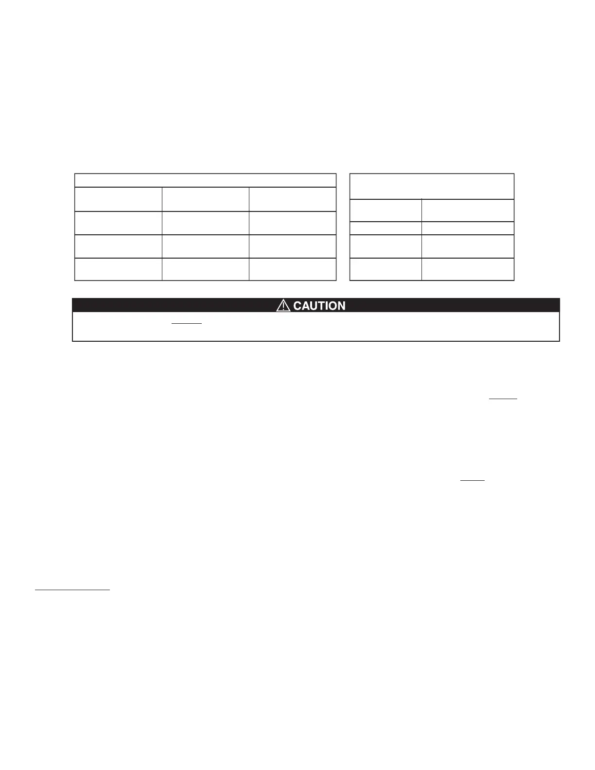
F. Set Screw and Taper-lock Bushing Torque Values:
All blower wheel set screws are tightened to the proper torque prior to shipment. Some wheels may have taper-lock
hubs and split, taper-lock bushings to secure the wheel to the blower shaft.
NOTE: Check all set screw or taper-lock bushing torques. Forces encountered during shipment, handling, rigging and
temperature can affect factory settings. For correct torque values, see Tables 1 and 2 below.
Set screws should NEVER be used more than once. If the set screws are loosened, they MUST be replaced.
Use only knurled, cup-point, set screws with a nylon locking patch.
G. Blower Bearings:
If the blower bearings have set screws to lock the bearings onto the blower shaft, the set screws should be tightened
to the same torque levels as shown in Table 1 above. Blower bearings should be lubricated in accordance with the
bearing manufacturer’s recommendation and with the same type of grease. See section B on page 9. Bearings are
pre-lubricated at the factory. Any blower shaft/bearing guard should only be removed for inspection before startup
and during inspection or maintenance, but only after the power to the motor has been turned off and locked out.
Any blower shaft/bearing guard MUST be replaced before the power is turned back on.
H. V-Belt Drives:
Since Cincinnati Fan did not supply the belts and sheaves (drives package), they must be carefully selected for the
specific operating conditions by the customer. The customer’s selection must NOT ALLOW the blower to exceed its
maximum safe speed. If you do not know the maximum safe speed for this blower, DO NOT make a drive selection
without first consulting Cincinnati Fan or our sales office for your area. “Timing” belts should never be used on any
blowers. The purchaser and/or user is responsible for installing the sheaves and belts for this blower in accordance
with the drive manufacturers instructions. This includes the proper alignment of the sheaves and tensioning of the
belt(s) so as not to cause excessive vibration of the blower assembly.
For complete drive installation instructions, please see the following websites:
www.emerson-ept.com/catalogs/instshts/browning/form5453.pdf
OR
www.maskapulleys.com/images/produit/Product%20Training_jan09.1.pdf
III. ELECTRICAL
A. Motors and Disconnects:
Since Cincinnati Fan does not supply any electrical components used with Arrangement 1 blower, it is the purchasers
and/or users responsibility to make sure all electrical components used with this blower are in compliance with any
and all company, local, state and federal regulations governing the use of this blower for the specific application it was
originally purchased for. This includes all component selection, proper installation and maintenance of any electrical
component or parts thereof.
B. Maximum Blower Speed with Motor Speed Controllers:
If you will be using any type of motor speed controller with this blower, DO NOT exceed the maximum safe
blower speed. It may be necessary to “block out” some speeds to eliminate a resonant vibration problem. The maxi-
mum safe blower speed is shown in the Blower Specifications section on page 1 of this manual. If you have lost
page 1, contact Cincinnati Fan or our sales office for your area. You must have the serial number from the blower
name plate for us to determine the maximum safe blower speed.
SET SCREW TORQUE VALUES
TORQUE VALUES FOR
TAPER-LOCK BUSHINGS
Diameter & Number
of Treads/Inch
Hex Wrence Size
(Across Flats)
Required Torque
(Inch Pounds)
1/4-20
5/16-18
3/8-16
7/16-14
1/2-13
5/8-11
1/8”
5/32”
3/16”
7/32”
1/4”
5/16”
65
165
228
348
504
1104
Taper-lock
Bushing Size
Required Torque
(Inch Pounds)
H
B
P
Q
R
95
192
192
350
350
T
able 2Table 1
 Loading...