15
Cisco 2500 Series Wireless Controller Getting Started Guide
Installing the Controller
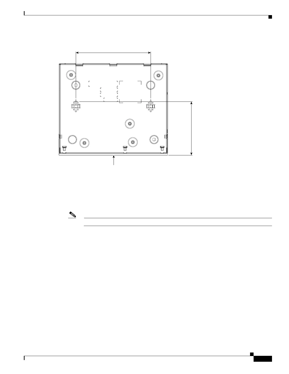
Figure 7 Mounting Screw Holes on the Back of the Controller
Step 2 Use a 0.107-inch (2.7mm) or #32 drill bit to drill a 3/4 inch (19mm) hole for the two mounting screws.
Step 3 Insert two screws into the screw holes and tighten until the top of the screws are 1/8 inch from the wall
(leaving enough room for the back panel to slide onto the screws firmly).
Step 4 Place the controller onto the mounting screws and slide it down until it lock into place, as shown in
Figure 8.
Note The front panel of the controller should be facing down.
282087
3.9
5.5
FRONT PANEL
 Loading...