16
Cisco 2500 Series Wireless Controller Getting Started Guide
Installing the Controller
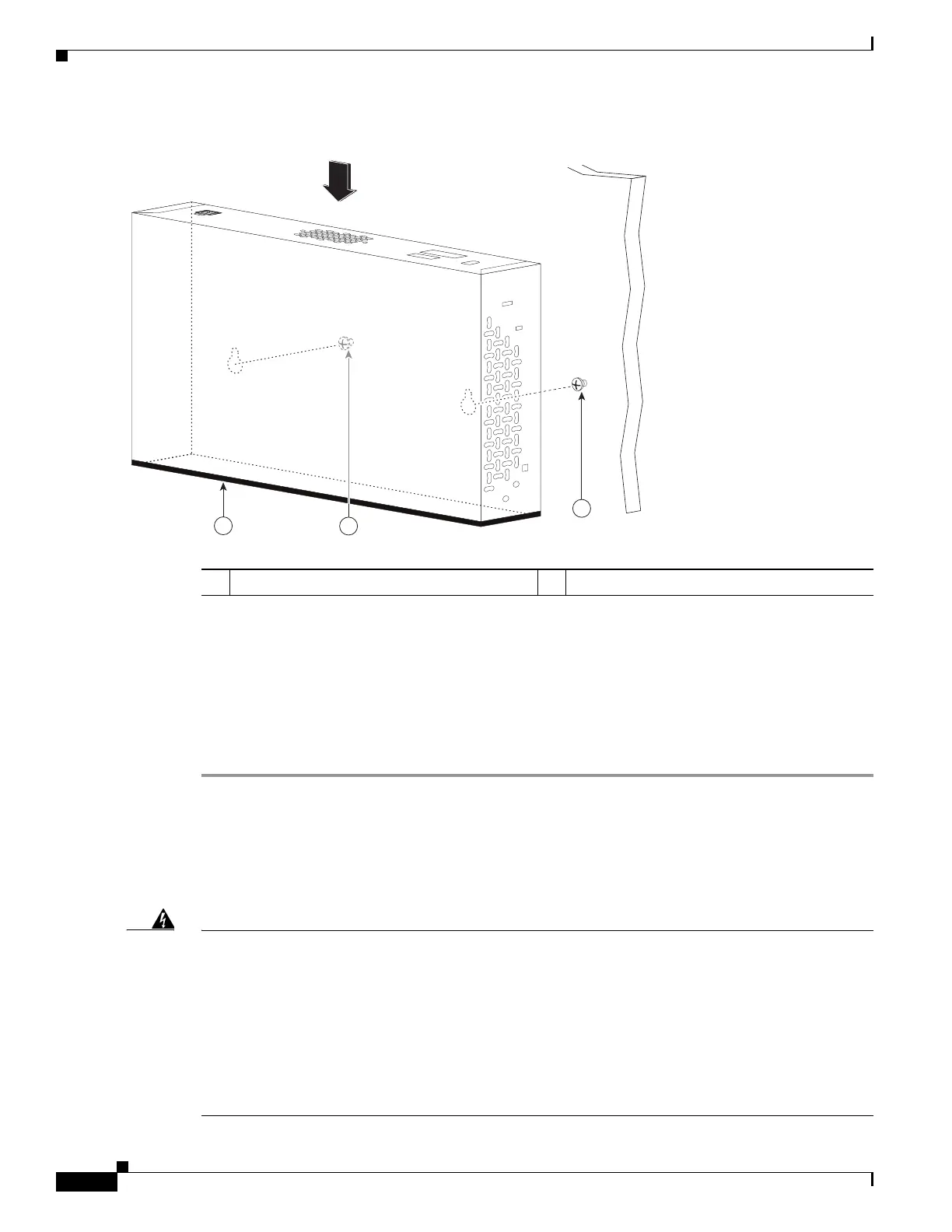
Figure 8 Place the Controller on the Mounting Screws
Step 5
After the controller is mounted ion the wall, perform the following tasks to complete the installation:
• Connecting the Controller Console Port
• Securing the Power Adapter Cable
• Connecting to the Network
Step 6 For configuration instructions about using the CLI setup program, see the “Running the Bootup Script
and Power-On Self Test” section on page 20.
Mounting the Controller in a Rack
To mount the 2504 controller in a 19-inch equipment rack, you can order an optional Optional Rack
Mount kit (AIR-CT2504-RMNT).
Warning
To prevent bodily injury when mounting or servicing this unit in a rack, you must take special precautions
to ensure that the system remains stable. The following guidelines are provided to ensure your safety:
• This unit should be mounted at the bottom of the rack if it is the only unit in the rack.
• When mounting this unit in a partially filled rack, load the rack from the bottom to the
top with the heaviest component at the bottom of the rack.
• If the rack is provided with stabilizing devices, install the stabilizers before mounting
or servicing the unit in the rack.
Statement 1006
1 Front panel (facing down) 2 Mounting screws
 Loading...