3-4
Cisco 3200 Series Router Hardware Upgrade Guide
OL-15983-01
Chapter 3 Replacing Cards in the Cisco ISR 3270 Rugged Enclosure
Card Replacement Process
Removing the I/O End Cap
To remove the I/O end cap, follow these steps:
Step 1 Use a 3/8-inch socket wrench to loosen the four 1/4-20 bolts on the end cap using a torque range of 58
to 68 in-lb.
Note If a protective end cap cover (see Figure 2-16) is used to provide weatherproof protection for the
ports on the I/O end cap, loosening the four 1/4-20 mounting bolts on the protective end cap
allows you to remove the protective end cap and the I/O end cap from the extrusion.
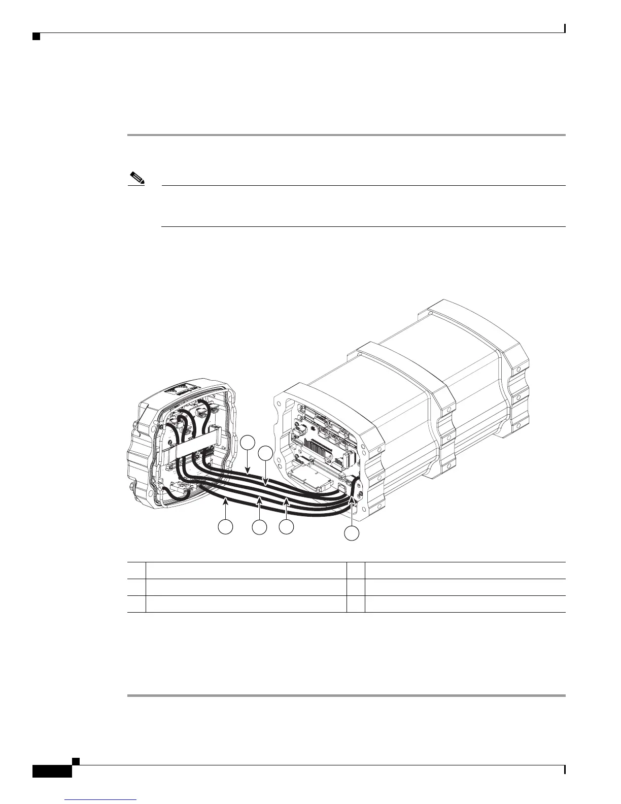
Step 2 Carefully pull off the end cap enough to give you enough room to disconnect the power cable. Figure 3-3
shows the cables.
Figure 3-3 Disconnecting the Power Cable
Step 3 Disconnect the power cable from the end cap.
Step 4 Slowly pull out the USB, FE 0, FE 1, GE 0, and GE 1 cables (which you already disconnected from the
card stack when you removed the antenna end cap) from beneath the card stack to free up the I/O end cap.
Step 5 Place the end cap on your work surface.
270467
6 5 4
3
1
2
1 GE 0 2 GE 1
3 FE extender cable 4 FE cable
5 USB cable 6 Power cable
 Loading...