92
Installing and Upgrading Internal Components in Cisco 3800 Series Routers
OL-5975-04
AIM Installation and Removal
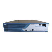
Figure 59 Plastic Standoff Orientation
Step 5
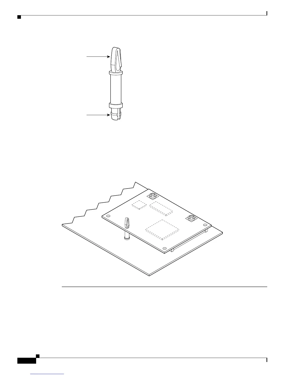
Insert the connector on the AIM into the connector on the motherboard. Press firmly on the AIM until it
seats onto the connector. The plastic standoff must snap into the hole in the AIM board. See Figure 60.
Step 6 Insert the machine-thread metal screws from the accessory kit through the AIM into the metal standoffs.
See Figure 60. Carefully tighten the screws with a number 1 Phillips screwdriver.
Step 7 Check that the AIM is installed correctly on the motherboard. See Figure 60.
Figure 60 AIM Installed on a Motherboard
82620
AIM end
Locking end
58696
 Loading...